
AutoCAD 2012
DXF Reference
February 2011
©
2011 Autodesk, Inc. All Rights Reserved. Except as otherwise permitted by Autodesk, Inc., this publication, or parts thereof, may not be
reproduced in any form, by any method, for any purpose.
Certain materials included in this publication are reprinted with the permission of the copyright holder.
Trademarks
The following are registered trademarks or trademarks of Autodesk, Inc., and/or its subsidiaries and/or affiliates in the USA and other countries:
3DEC (design/logo), 3December, 3December.com, 3ds Max, Algor, Alias, Alias (swirl design/logo), AliasStudio, Alias|Wavefront (design/logo),
ATC, AUGI, AutoCAD, AutoCAD Learning Assistance, AutoCAD LT, AutoCAD Simulator, AutoCAD SQL Extension, AutoCAD SQL Interface,
Autodesk, Autodesk Intent, Autodesk Inventor, Autodesk MapGuide, Autodesk Streamline, AutoLISP, AutoSnap, AutoSketch, AutoTrack, Backburner,
Backdraft, Beast, Built with ObjectARX (logo), Burn, Buzzsaw, CAiCE, Civil 3D, Cleaner, Cleaner Central, ClearScale, Colour Warper, Combustion,
Communication Specification, Constructware, Content Explorer, Dancing Baby (image), DesignCenter, Design Doctor, Designer's Toolkit,
DesignKids, DesignProf, DesignServer, DesignStudio, Design Web Format, Discreet, DWF, DWG, DWG (logo), DWG Extreme, DWG TrueConvert,
DWG TrueView, DXF, Ecotect, Exposure, Extending the Design Team, Face Robot, FBX, Fempro, Fire, Flame, Flare, Flint, FMDesktop, Freewheel,
GDX Driver, Green Building Studio, Heads-up Design, Heidi, HumanIK, IDEA Server, i-drop, Illuminate Labs AB (design/logo), ImageModeler,
iMOUT, Incinerator, Inferno, Inventor, Inventor LT, Kynapse, Kynogon, LandXplorer, LiquidLight, LiquidLight (design/logo), Lustre, MatchMover,
Maya, Mechanical Desktop, Moldflow, Moldflow Plastics Advisers, MPI, Moldflow Plastics Insight, Moldflow Plastics Xpert, Moondust, MotionBuilder,
Movimento, MPA, MPA (design/logo), MPX, MPX (design/logo), Mudbox, Multi-Master Editing, Navisworks, ObjectARX, ObjectDBX, Opticore,
Pipeplus, PolarSnap, PortfolioWall, Powered with Autodesk Technology, Productstream, ProMaterials, RasterDWG, RealDWG, Real-time Roto,
Recognize, Render Queue, Retimer, Reveal, Revit, RiverCAD, Robot, Showcase, Show Me, ShowMotion, SketchBook, Smoke, Softimage,
Softimage|XSI (design/logo), Sparks, SteeringWheels, Stitcher, Stone, StormNET, StudioTools, ToolClip, Topobase, Toxik, TrustedDWG, U-Vis,
ViewCube, Visual, Visual LISP, Volo, Vtour, WaterNetworks, Wire, Wiretap, WiretapCentral, XSI.
All other brand names, product names or trademarks belong to their respective holders.
Disclaimer
THIS PUBLICATION AND THE INFORMATION CONTAINED HEREIN IS MADE AVAILABLE BY AUTODESK, INC. "AS IS." AUTODESK, INC. DISCLAIMS
ALL WARRANTIES, EITHER EXPRESS OR IMPLIED, INCLUDING BUT NOT LIMITED TO ANY IMPLIED WARRANTIES OF MERCHANTABILITY OR
FITNESS FOR A PARTICULAR PURPOSE REGARDING THESE MATERIALS.
Published by:
Autodesk, Inc.
111 McInnis Parkway
San Rafael, CA 94903, USA
Contents
Chapter 1 DXF Format . . . . . . . . . . . . . . . . . . . . . . . . . . . . . 1
Organization of This Reference . . . . . . . . . . . . . . . . . . . . . . . 1
Revisions to the DXF Reference . . . . . . . . . . . . . . . . . . . . . . 1
Formatting Conventions in This Reference . . . . . . . . . . . . . . . . 2
Object and Entity Codes . . . . . . . . . . . . . . . . . . . . . . . . . . 2
Group Code Value Types . . . . . . . . . . . . . . . . . . . . . . . . . . 3
Group Codes in Numerical Order . . . . . . . . . . . . . . . . . . . . . 5
Chapter 2 HEADER Section . . . . . . . . . . . . . . . . . . . . . . . . . . 11
HEADER Section Group Codes . . . . . . . . . . . . . . . . . . . . . . 11
Revised VPORT Header Variables . . . . . . . . . . . . . . . . . . 28
Special Handling of Date/Time Variables . . . . . . . . . . . . . . 29
Chapter 3 CLASSES Section . . . . . . . . . . . . . . . . . . . . . . . . . . 31
CLASSES Section Group Codes . . . . . . . . . . . . . . . . . . . . . . 31
Default Class Values . . . . . . . . . . . . . . . . . . . . . . . . . 32
Chapter 4 TABLES Section . . . . . . . . . . . . . . . . . . . . . . . . . . 35
Symbol Table Group Codes . . . . . . . . . . . . . . . . . . . . . . . . 35
Common Symbol Table Group Codes . . . . . . . . . . . . . . . . . . 36
Common Group Codes for Symbol Table Entries . . . . . . . . . 37
APPID . . . . . . . . . . . . . . . . . . . . . . . . . . . . . . . . . . . 38
iii
BLOCK_RECORD . . . . . . . . . . . . . . . . . . . . . . . . . . . . . 38
DIMSTYLE . . . . . . . . . . . . . . . . . . . . . . . . . . . . . . . . . 39
LAYER . . . . . . . . . . . . . . . . . . . . . . . . . . . . . . . . . . . 43
LTYPE . . . . . . . . . . . . . . . . . . . . . . . . . . . . . . . . . . . 44
STYLE . . . . . . . . . . . . . . . . . . . . . . . . . . . . . . . . . . . 46
UCS . . . . . . . . . . . . . . . . . . . . . . . . . . . . . . . . . . . . 47
VIEW . . . . . . . . . . . . . . . . . . . . . . . . . . . . . . . . . . . 49
VPORT . . . . . . . . . . . . . . . . . . . . . . . . . . . . . . . . . . . 52
Chapter 5 BLOCKS Section . . . . . . . . . . . . . . . . . . . . . . . . . . 57
BLOCKS Section Group Codes . . . . . . . . . . . . . . . . . . . . . . 57
BLOCK . . . . . . . . . . . . . . . . . . . . . . . . . . . . . . . . . . . 58
ENDBLK . . . . . . . . . . . . . . . . . . . . . . . . . . . . . . . . . . 59
Chapter 6 ENTITIES Section . . . . . . . . . . . . . . . . . . . . . . . . . 61
Common Group Codes for Entities . . . . . . . . . . . . . . . . . . . . 61
3DFACE . . . . . . . . . . . . . . . . . . . . . . . . . . . . . . . . . . 64
3DSOLID . . . . . . . . . . . . . . . . . . . . . . . . . . . . . . . . . . 65
ACAD_PROXY_ENTITY . . . . . . . . . . . . . . . . . . . . . . . . . . 65
ARC . . . . . . . . . . . . . . . . . . . . . . . . . . . . . . . . . . . . 66
ATTDEF . . . . . . . . . . . . . . . . . . . . . . . . . . . . . . . . . . 67
ATTRIB . . . . . . . . . . . . . . . . . . . . . . . . . . . . . . . . . . . 72
BODY . . . . . . . . . . . . . . . . . . . . . . . . . . . . . . . . . . . 77
CIRCLE . . . . . . . . . . . . . . . . . . . . . . . . . . . . . . . . . . 77
DIMENSION . . . . . . . . . . . . . . . . . . . . . . . . . . . . . . . . 78
Common Dimension Group Codes . . . . . . . . . . . . . . . . . 78
Aligned Dimension Group Codes . . . . . . . . . . . . . . . . . . 80
Linear and Rotated Dimension Group Codes . . . . . . . . . . . . 81
Radial and Diameter Dimension Group Codes . . . . . . . . . . . 82
Angular Dimension Group Codes . . . . . . . . . . . . . . . . . . 83
Ordinate Dimension Group Codes . . . . . . . . . . . . . . . . . 85
Dimension Style Overrides . . . . . . . . . . . . . . . . . . . . . 86
ELLIPSE . . . . . . . . . . . . . . . . . . . . . . . . . . . . . . . . . . 86
HATCH . . . . . . . . . . . . . . . . . . . . . . . . . . . . . . . . . . 87
Boundary Path Data . . . . . . . . . . . . . . . . . . . . . . . . . 90
Pattern Data . . . . . . . . . . . . . . . . . . . . . . . . . . . . . 94
HELIX . . . . . . . . . . . . . . . . . . . . . . . . . . . . . . . . . . . 94
IMAGE . . . . . . . . . . . . . . . . . . . . . . . . . . . . . . . . . . . 95
INSERT . . . . . . . . . . . . . . . . . . . . . . . . . . . . . . . . . . . 97
LEADER . . . . . . . . . . . . . . . . . . . . . . . . . . . . . . . . . . 98
LIGHT . . . . . . . . . . . . . . . . . . . . . . . . . . . . . . . . . . 100
LINE . . . . . . . . . . . . . . . . . . . . . . . . . . . . . . . . . . . 101
LWPOLYLINE . . . . . . . . . . . . . . . . . . . . . . . . . . . . . . . 102
MESH . . . . . . . . . . . . . . . . . . . . . . . . . . . . . . . . . . . 103
MLINE . . . . . . . . . . . . . . . . . . . . . . . . . . . . . . . . . . 104
iv | Contents
MLEADERSTYLE . . . . . . . . . . . . . . . . . . . . . . . . . . . . . 107
MLEADER . . . . . . . . . . . . . . . . . . . . . . . . . . . . . . . . 109
Common MLeader Group Codes . . . . . . . . . . . . . . . . . 110
MLeader Context Data Group Codes . . . . . . . . . . . . . . . 112
MLeader Leader Node Group Codes . . . . . . . . . . . . . . . . 116
MLeader Leader Line Group Codes . . . . . . . . . . . . . . . . 117
MTEXT . . . . . . . . . . . . . . . . . . . . . . . . . . . . . . . . . . 117
OLEFRAME . . . . . . . . . . . . . . . . . . . . . . . . . . . . . . . . 120
OLE2FRAME . . . . . . . . . . . . . . . . . . . . . . . . . . . . . . . 120
POINT . . . . . . . . . . . . . . . . . . . . . . . . . . . . . . . . . . 123
POLYLINE . . . . . . . . . . . . . . . . . . . . . . . . . . . . . . . . 123
Polyface Meshes . . . . . . . . . . . . . . . . . . . . . . . . . . 125
RAY . . . . . . . . . . . . . . . . . . . . . . . . . . . . . . . . . . . . 126
REGION . . . . . . . . . . . . . . . . . . . . . . . . . . . . . . . . . 126
SECTION . . . . . . . . . . . . . . . . . . . . . . . . . . . . . . . . . 127
SEQEND . . . . . . . . . . . . . . . . . . . . . . . . . . . . . . . . . 128
SHAPE . . . . . . . . . . . . . . . . . . . . . . . . . . . . . . . . . . 128
SOLID . . . . . . . . . . . . . . . . . . . . . . . . . . . . . . . . . . 129
SPLINE . . . . . . . . . . . . . . . . . . . . . . . . . . . . . . . . . . 130
SUN . . . . . . . . . . . . . . . . . . . . . . . . . . . . . . . . . . . . 132
SURFACE . . . . . . . . . . . . . . . . . . . . . . . . . . . . . . . . . 133
Extruded Surface . . . . . . . . . . . . . . . . . . . . . . . . . . 133
Lofted Surface . . . . . . . . . . . . . . . . . . . . . . . . . . . 135
Revolved Surface . . . . . . . . . . . . . . . . . . . . . . . . . . 136
Swept Surface . . . . . . . . . . . . . . . . . . . . . . . . . . . 137
TABLE . . . . . . . . . . . . . . . . . . . . . . . . . . . . . . . . . . 138
TEXT . . . . . . . . . . . . . . . . . . . . . . . . . . . . . . . . . . . 144
TOLERANCE . . . . . . . . . . . . . . . . . . . . . . . . . . . . . . . 146
TRACE . . . . . . . . . . . . . . . . . . . . . . . . . . . . . . . . . . 146
UNDERLAY . . . . . . . . . . . . . . . . . . . . . . . . . . . . . . . . 147
VERTEX . . . . . . . . . . . . . . . . . . . . . . . . . . . . . . . . . 149
VIEWPORT . . . . . . . . . . . . . . . . . . . . . . . . . . . . . . . . 150
WIPEOUT . . . . . . . . . . . . . . . . . . . . . . . . . . . . . . . . 155
XLINE . . . . . . . . . . . . . . . . . . . . . . . . . . . . . . . . . . 157
Chapter 7 OBJECTS Section . . . . . . . . . . . . . . . . . . . . . . . . . 159
OBJECT Section Group Codes . . . . . . . . . . . . . . . . . . . . . . 159
Object Ownership . . . . . . . . . . . . . . . . . . . . . . . . . 159
Common Group Codes for Objects . . . . . . . . . . . . . . . . . . . 160
ACAD_PROXY_OBJECT . . . . . . . . . . . . . . . . . . . . . . . . . 161
ACDBDICTIONARYWDFLT . . . . . . . . . . . . . . . . . . . . . . . 161
ACDBPLACEHOLDER . . . . . . . . . . . . . . . . . . . . . . . . . . 162
DATATABLE . . . . . . . . . . . . . . . . . . . . . . . . . . . . . . . 163
DICTIONARY . . . . . . . . . . . . . . . . . . . . . . . . . . . . . . . 164
DICTIONARYVAR . . . . . . . . . . . . . . . . . . . . . . . . . . . . 166
DIMASSOC . . . . . . . . . . . . . . . . . . . . . . . . . . . . . . . . 166
Contents | v
FIELD . . . . . . . . . . . . . . . . . . . . . . . . . . . . . . . . . . . 168
GEODATA . . . . . . . . . . . . . . . . . . . . . . . . . . . . . . . . 170
GROUP . . . . . . . . . . . . . . . . . . . . . . . . . . . . . . . . . . 172
IDBUFFER . . . . . . . . . . . . . . . . . . . . . . . . . . . . . . . . 173
IMAGEDEF . . . . . . . . . . . . . . . . . . . . . . . . . . . . . . . . 173
IMAGEDEF_REACTOR . . . . . . . . . . . . . . . . . . . . . . . . . . 174
LAYER_INDEX . . . . . . . . . . . . . . . . . . . . . . . . . . . . . . 175
LAYER_FILTER . . . . . . . . . . . . . . . . . . . . . . . . . . . . . . 175
LAYOUT . . . . . . . . . . . . . . . . . . . . . . . . . . . . . . . . . 176
LIGHTLIST . . . . . . . . . . . . . . . . . . . . . . . . . . . . . . . . 179
MATERIAL . . . . . . . . . . . . . . . . . . . . . . . . . . . . . . . . 179
MLINESTYLE . . . . . . . . . . . . . . . . . . . . . . . . . . . . . . . 186
OBJECT_PTR . . . . . . . . . . . . . . . . . . . . . . . . . . . . . . . 188
PLOTSETTINGS . . . . . . . . . . . . . . . . . . . . . . . . . . . . . 189
RASTERVARIABLES . . . . . . . . . . . . . . . . . . . . . . . . . . . . 192
RENDER . . . . . . . . . . . . . . . . . . . . . . . . . . . . . . . . . 193
RENDERENVIRONMENT . . . . . . . . . . . . . . . . . . . . . 193
MENTALRAYRENDERSETTINGS . . . . . . . . . . . . . . . . . . 194
RENDERGLOBAL . . . . . . . . . . . . . . . . . . . . . . . . . . 197
SECTION . . . . . . . . . . . . . . . . . . . . . . . . . . . . . . . . . 198
Section Manager . . . . . . . . . . . . . . . . . . . . . . . . . . 199
Section Settings . . . . . . . . . . . . . . . . . . . . . . . . . . 199
Section Type Settings . . . . . . . . . . . . . . . . . . . . . . . 200
Section Geometry Settings . . . . . . . . . . . . . . . . . . . . . 201
SPATIAL_INDEX . . . . . . . . . . . . . . . . . . . . . . . . . . . . . 202
SPATIAL_FILTER . . . . . . . . . . . . . . . . . . . . . . . . . . . . . 203
SORTENTSTABLE . . . . . . . . . . . . . . . . . . . . . . . . . . . . . 204
TABLESTYLE . . . . . . . . . . . . . . . . . . . . . . . . . . . . . . . 205
UNDERLAYDEFINITION . . . . . . . . . . . . . . . . . . . . . . . . . 207
VISUALSTYLE . . . . . . . . . . . . . . . . . . . . . . . . . . . . . . 208
VBA_PROJECT . . . . . . . . . . . . . . . . . . . . . . . . . . . . . . 211
WIPEOUTVARIABLES . . . . . . . . . . . . . . . . . . . . . . . . . . 211
XRECORD . . . . . . . . . . . . . . . . . . . . . . . . . . . . . . . . 212
Chapter 8 THUMBNAILIMAGE Section . . . . . . . . . . . . . . . . . . . 215
THUMBNAILIMAGE Section Group Codes . . . . . . . . . . . . . . . 215
Chapter 9 Drawing Interchange File Formats . . . . . . . . . . . . . . . 217
ASCII DXF Files . . . . . . . . . . . . . . . . . . . . . . . . . . . . . 217
General DXF File Structure . . . . . . . . . . . . . . . . . . . . 217
Group Codes in DXF Files . . . . . . . . . . . . . . . . . . . . . 219
ASCII Control Characters in DXF Files . . . . . . . . . . . 219
Header Group Codes in DXF Files . . . . . . . . . . . . . . . . . 219
Class Group Codes in DXF Files . . . . . . . . . . . . . . . . . . 220
Symbol Table Group Codes in DXF Files . . . . . . . . . . . . . 220
vi | Contents
Symbol Table Example . . . . . . . . . . . . . . . . . . . 221
Blocks Group Codes in DXF Files . . . . . . . . . . . . . . . . . 224
Entity Group Codes in DXF Files . . . . . . . . . . . . . . . . . 226
Object Group Codes in DXF Files . . . . . . . . . . . . . . . . . 226
Writing a DXF Interface Program . . . . . . . . . . . . . . . . . 227
Reading a DXF File . . . . . . . . . . . . . . . . . . . . . . 228
Writing a DXF File . . . . . . . . . . . . . . . . . . . . . . 230
Binary DXF Files . . . . . . . . . . . . . . . . . . . . . . . . . . . . . 234
Slide Files . . . . . . . . . . . . . . . . . . . . . . . . . . . . . . . . . 235
Old Slide Header . . . . . . . . . . . . . . . . . . . . . . . . . . 238
Slide Library Files . . . . . . . . . . . . . . . . . . . . . . . . . . . . 239
Chapter 10 Advanced DXF Issues . . . . . . . . . . . . . . . . . . . . . . 241
Database Objects . . . . . . . . . . . . . . . . . . . . . . . . . . . . . 241
Persistent Inter-Object Reference Handles . . . . . . . . . . . . . . . . 241
Pointer and Ownership References . . . . . . . . . . . . . . . . 242
Hard and Soft References . . . . . . . . . . . . . . . . . . . . . 242
Arbitrary Handles . . . . . . . . . . . . . . . . . . . . . . . . . 243
1005 Group Codes . . . . . . . . . . . . . . . . . . . . . . . . . 243
Subclass Markers . . . . . . . . . . . . . . . . . . . . . . . . . . . . . 243
Extension Dictionary and Persistent Reactors . . . . . . . . . . . . . . 246
Extended Data . . . . . . . . . . . . . . . . . . . . . . . . . . . . . . 246
Object Coordinate Systems (OCS) . . . . . . . . . . . . . . . . . . . . 250
Arbitrary Axis Algorithm . . . . . . . . . . . . . . . . . . . . . . . . . 252
Index . . . . . . . . . . . . . . . . . . . . . . . . . . . . . . . 253
Contents | vii
viii
DXF Format
The DXF
™
format is a tagged data representation of all the information contained in an
AutoCAD
®
drawing file. Tagged data means that each data element in the file is preceded by
an integer number that is called a group code. A group code's value indicates what type of data
element follows. This value also indicates the meaning of a data element for a given object
(or record) type. Virtually all user-specified information in a drawing file can be represented
in DXF format.
Organization of This Reference
The DXF Reference presents the DXF
™
group codes found in DXF files and
encountered by AutoLISP
®
and ObjectARX
®
applications. This chapter describes
the general DXF conventions. The remaining chapters list the group codes
organized by object type. The group codes are presented in the order in which
they are found in a DXF file, and each chapter is named according to the
associated section of a DXF file. Although the DXF file format is used as the
organizing mechanism for this reference, specific information on the actual
formatting of DXF files is found in Drawing Interchange File Formats on page
217 Advanced concepts relating to DXF group codes as they pertain to both
applications and DXF files are found in Advanced DXF Issues on page 241
For descriptions of the AutoLISP functions that use group codes, see "Using
AutoLISP to Manipulate AutoCAD Objects" in the AutoLISP Developer's Guide.
Revisions to the DXF Reference
This topic lists revisions since the last update of the DXF Reference. The version
number of this DXF Reference is u19.1.01.
■ “ENTITIES Section”
1
1

■ “OBJECTS Section”
Formatting Conventions in This Reference
Each group code listed in this reference is presented by a numeric group code
value and a description. All group codes can apply to DXF
™
files, applications
(AutoLISP or ObjectARX), or both. When the description of a code is different
for applications and DXF files (or applies to only one or the other), the
description is preceded by the following indicators:
■ APP.Application-specific description.
■ DXF.DXF file-specific description.
If the description is common to both DXF files and applications, no indicator
is provided.
Optional codes are indicated as “optional” in the description.
Object and Entity Codes
In the DXF
™
format, the definition of objects differs from entities: objects
have no graphical representation and entities do. For example, dictionaries
are objects, and not entities. Entities are also referred to as graphical objects
while objects are referred to as nongraphical objects.
Entities appear in both the BLOCK and ENTITIES sections of the DXF file. The
use of group codes in the two sections is identical.
Some group codes that define an entity always appear; others are optional
and appear only if their values differ from the defaults.
Do not write programs that rely on the order given here. The end of an entity
is indicated by the next 0 group, which begins the next entity or indicates the
end of the section.
NOTE Accommodating DXF files from future releases of AutoCAD
®
will be easier
if you write your DXF processing program in a table-driven way, ignore undefined
group codes, and make no assumptions about the order of group codes in an
entity. With each new AutoCAD release, new group codes will be added to entities
to accommodate additional features.
2 | Chapter 1 DXF Format

Group Code Value Types
Group codes define the type of the associated value as an integer, a
floating-point number, or a string, according to the following table of group
code ranges. For information about abbreviations and formatting used in this
table, see Formatting Conventions in This Reference on page 2.
Group code value types
Group value typeCode range
String (with the introduction of extended symbol names in AutoCAD 2000, the 255-character
limit has been increased to 2049 single-byte characters not including the newline at the end
of the line)
0-9
Double precision 3D point value10-39
Double-precision floating-point value40-59
16-bit integer value60-79
32-bit integer value90-99
String (255-character maximum; less for Unicode strings)100
String (255-character maximum; less for Unicode strings)102
String representing hexadecimal (hex) handle value105
Double precision floating-point value110-119
Double precision floating-point value120-129
Double precision floating-point value130-139
Double precision scalar floating-point value140-149
64-bit integer value160-169
16-bit integer value170-179
Double-precision floating-point value210-239
16-bit integer value270-279
Group Code Value Types | 3

Group code value types
Group value typeCode range
16-bit integer value280-289
Boolean flag value290-299
Arbitrary text string300-309
String representing hex value of binary chunk310-319
String representing hex handle value320-329
String representing hex object IDs330-369
16-bit integer value370-379
16-bit integer value380-389
String representing hex handle value390-399
16-bit integer value400-409
String410-419
32-bit integer value420-429
String430-439
32-bit integer value440-449
Long450-459
Double-precision floating-point value460-469
String470-479
String representing hex handle value480-481
Comment (string)999
String (same limits as indicated with 0-9 code range)1000-1009
4 | Chapter 1 DXF Format
Group code value types
Group value typeCode range
Double-precision floating-point value1010-1059
16-bit integer value1060-1070
32-bit integer value1071
Group Codes in Numerical Order
The following table gives the group code or group code range accompanied
by an explanation of the group code value. In the table, “fixed” indicates that
the group code always has the same purpose. If a group code isn't fixed, its
purpose depends on the context. For information about abbreviations and
formatting used in this table, see Formatting Conventions in This Reference
on page 2.
Group codes by number
DescriptionGroup code
APP: persistent reactor chain-5
APP: conditional operator (used only with ssget)-4
APP: extended data (XDATA) sentinel (fixed)-3
APP: entity name reference (fixed)-2
APP: entity name. The name changes each time a drawing is opened. It is never saved (fixed)-1
Text string indicating the entity type (fixed)0
Primary text value for an entity1
Name (attribute tag, block name, and so on)2
Other text or name values3-4
Entity handle; text string of up to 16 hexadecimal digits (fixed)5
Linetype name (fixed)6
Group Codes in Numerical Order | 5
Group codes by number
DescriptionGroup code
Text style name (fixed)7
Layer name (fixed)8
DXF: variable name identifier (used only in HEADER section of the DXF file)9
Primary point; this is the start point of a line or text entity, center of a circle, and so on10
DXF: X value of the primary point (followed by Y and Z value codes 20 and 30)
APP: 3D point (list of three reals)
Other points11-18
DXF: X value of other points (followed by Y value codes 21-28 and Z value codes 31-38)
APP: 3D point (list of three reals)
DXF: Y and Z values of the primary point20, 30
DXF: Y and Z values of other points21-28, 31-37
DXF: entity's elevation if nonzero38
Entity's thickness if nonzero (fixed)39
Double-precision floating-point values (text height, scale factors, and so on)40-48
Linetype scale; double precision floating point scalar value; default value is defined for all entity
types
48
Repeated double-precision floating-point value. Multiple 49 groups may appear in one entity
for variable-length tables (such as the dash lengths in the LTYPE table). A 7x group always appears
before the first 49 group to specify the table length
49
Angles (output in degrees to DXF files and radians through AutoLISP and ObjectARX applications)50-58
Entity visibility; integer value; absence or 0 indicates visibility; 1indicates invisibility60
Color number (fixed)62
“Entities follow” flag (fixed)66
Space—that is, model or paper space (fixed)67
6 | Chapter 1 DXF Format

Group codes by number
DescriptionGroup code
APP: identifies whether viewport is on but fully off screen; is not active or is off68
APP: viewport identification number69
Integer values, such as repeat counts, flag bits, or modes70-78
32-bit integer values90-99
Subclass data marker (with derived class name as a string). Required for all objects and entity
classes that are derived from another concrete class. The subclass data marker segregates data
defined by different classes in the inheritance chain for the same object.
100
This is in addition to the requirement for DXF names for each distinct concrete class derived
from ObjectARX (see Subclass Markers on page 243)
Control string, followed by “{<arbitrary name>” or “}”. Similar to the xdata 1002 group code,
except that when the string begins with “{“, it can be followed by an arbitrary string whose
102
interpretation is up to the application. The only other control string allowed is “}” as a group
terminator. AutoCAD does not interpret these strings except during drawing audit operations.
They are for application use
Object handle for DIMVAR symbol table entry105
UCS origin (appears only if code 72 is set to 1)110
DXF: X value; APP: 3D point
UCS X-axis (appears only if code 72 is set to 1)111
DXF: X value; APP: 3D vector
UCS Y-axis (appears only if code 72 is set to 1)112
DXF: X value; APP: 3D vector
DXF: Y value of UCS origin, UCS X-axis, and UCS Y-axis120-122
DXF: Z value of UCS origin, UCS X-axis, and UCS Y-axis130-132
Double-precision floating-point values (points, elevation, and DIMSTYLE settings, for example)140-149
16-bit integer values, such as flag bits representing DIMSTYLE settings170-179
Extrusion direction (fixed)210
Group Codes in Numerical Order | 7

Group codes by number
DescriptionGroup code
DXF: X value of extrusion direction
APP: 3D extrusion direction vector
DXF: Y and Z values of the extrusion direction220, 230
16-bit integer values270-279
16-bit integer value280-289
Boolean flag value290-299
Arbitrary text strings300-309
Arbitrary binary chunks with same representation and limits as 1004 group codes: hexadecimal
strings of up to 254 characters represent data chunks of up to 127 bytes
310-319
Arbitrary object handles; handle values that are taken “as is”. They are not translated during
INSERT and XREF operations
320-329
Soft-pointer handle; arbitrary soft pointers to other objects within same DXF file or drawing.
Translated during INSERT and XREF operations
330-339
Hard-pointer handle; arbitrary hard pointers to other objects within same DXF file or drawing.
Translated during INSERT and XREF operations
340-349
Soft-owner handle; arbitrary soft ownership links to other objects within same DXF file or
drawing. Translated during INSERT and XREF operations
350-359
Hard-owner handle; arbitrary hard ownership links to other objects within same DXF file or
drawing. Translated during INSERT and XREF operations
360-369
Lineweight enum value (AcDb::LineWeight). Stored and moved around as a 16-bit integer.
Custom non-entity objects may use the full range, but entity classes only use 371-379 DXF
370-379
group codes in their representation, because AutoCAD and AutoLISP both always assume a
370 group code is the entity's lineweight. This allows 370 to behave like other “common” entity
fields
PlotStyleName type enum (AcDb::PlotStyleNameType). Stored and moved around as a 16-bit
integer. Custom non-entity objects may use the full range, but entity classes only use 381-389
DXF group codes in their representation, for the same reason as the Lineweight range above
380-389
8 | Chapter 1 DXF Format
Group codes by number
DescriptionGroup code
String representing handle value of the PlotStyleName object, basically a hard pointer, but has
a different range to make backward compatibility easier to deal with. Stored and moved around
390-399
as an object ID (a handle in DXF files) and a special type in AutoLISP. Custom non-entity objects
may use the full range, but entity classes only use 391-399 DXF group codes in their represent-
ation, for the same reason as the lineweight range above
16-bit integers400-409
String410-419
32-bit integer value. When used with True Color; a 32-bit integer representing a 24-bit color
value. The high-order byte (8 bits) is 0, the low-order byte an unsigned char holding the Blue
420-427
value (0-255), then the Green value, and the next-to-high order byte is the Red Value. Convering
this integer value to hexadecimal yields the following bit mask: 0x00RRGGBB. For example, a
true color with Red==200, Green==100 and Blue==50 is 0x00C86432, and in DXF, in decimal,
13132850
String; when used for True Color, a string representing the name of the color430-437
32-bit integer value. When used for True Color, the transparency value440-447
Long450-459
Double-precision floating-point value460-469
String470-479
Hard-pointer handle; arbitrary hard pointers to other objects within same DXF file or drawing.
Translated during INSERT and XREF operations
480-481
DXF: The 999 group code indicates that the line following it is a comment string. SAVEAS does
not include such groups in a DXF output file, but OPEN honors them and ignores the comments.
You can use the 999 group to include comments in a DXF file that you've edited
999
ASCII string (up to 255 bytes long) in extended data1000
Registered application name (ASCII string up to 31 bytes long) for extended data1001
Extended data control string (“{” or “}”)1002
Group Codes in Numerical Order | 9

Group codes by number
DescriptionGroup code
Extended data layer name1003
Chunk of bytes (up to 127 bytes long) in extended data1004
Entity handle in extended data; text string of up to 16 hexadecimal digits1005
A point in extended data1010
DXF: X value (followed by 1020 and 1030 groups)
APP: 3D point
DXF: Y and Z values of a point1020, 1030
A 3D world space position in extended data1011
DXF: X value (followed by 1021 and 1031 groups)
APP: 3D point
DXF: Y and Z values of a world space position1021, 1031
A 3D world space displacement in extended data1012
DXF: X value (followed by 1022 and 1032 groups)
APP: 3D vector
DXF: Y and Z values of a world space displacement1022, 1032
A 3D world space direction in extended data1013
DXF: X value (followed by 1022 and 1032 groups)
APP: 3D vector
DXF: Y and Z values of a world space direction1023, 1033
Extended data double-precision floating-point value1040
Extended data distance value1041
Extended data scale factor1042
Extended data 16-bit signed integer1070
Extended data 32-bit signed long1071
10 | Chapter 1 DXF Format

HEADER Section
The group codes described in this chapter pertain only to DXF
™
files. The HEADER section
of a DXF file contains the settings of variables associated with the drawing. Each variable is
specified by a 9 group code giving the variable's name, followed by groups that supply the
variable's value. This chapter lists only the variables that are saved in the drawing file.
HEADER Section Group Codes
The following table lists the variables that are represented in the HEADER section
of a DXF
™
file. For information about abbreviations and formatting used in this
table, see Formatting Conventions in This Reference on page 2.
DXF header variables
DescriptionGroup codeVariable
Maintenance version number (should be ignored)70$ACADMAINTVER
The AutoCAD drawing database version number:1$ACADVER
AC1006 = R10;
AC1009 = R11 and R12;
AC1012 = R13; AC1014 = R14;
AC1015 = AutoCAD 2000;
AC1018 = AutoCAD 2004;
AC1021 = AutoCAD 2007;
AC1024 = AutoCAD 2010
Angle 0 direction50$ANGBASE
1 = Clockwise angles70$ANGDIR
0 = Counterclockwise angles
2
11

DXF header variables
DescriptionGroup codeVariable
Attribute visibility:70$ATTMODE
0 = None
1 = Normal
2 = All
Units format for angles70$AUNITS
Units precision for angles70$AUPREC
Current entity color number:62$CECOLOR
0 = BYBLOCK; 256 = BYLAYER
Current entity linetype scale40$CELTSCALE
Entity linetype name, or BYBLOCK or BYLAYER6$CELTYPE
Lineweight of new objects370$CELWEIGHT
Plotstyle handle of new objects; if CEPSNTYPE is 3, then
this value indicates the handle
390$CEPSNID
Plot style type of new objects:380$CEPSNTYPE
0 = Plot style by layer
1 = Plot style by block
2 = Plot style by dictionary default
3 = Plot style by object ID/handle
First chamfer distance40$CHAMFERA
Second chamfer distance40$CHAMFERB
Chamfer length40$CHAMFERC
Chamfer angle40$CHAMFERD
Current layer name8$CLAYER
Current multiline justification:70$CMLJUST
0 = Top; 1 = Middle; 2 = Bottom
12 | Chapter 2 HEADER Section

DXF header variables
DescriptionGroup codeVariable
Current multiline scale40$CMLSCALE
Current multiline style name2$CMLSTYLE
Shadow mode for a 3D object:280$CSHADOW
0 = Casts and receives shadows
1 = Casts shadows
2 = Receives shadows
3 = Ignores shadows
Number of precision places displayed in angular dimensions70$DIMADEC
Alternate unit dimensioning performed if nonzero70$DIMALT
Alternate unit decimal places70$DIMALTD
Alternate unit scale factor40$DIMALTF
Determines rounding of alternate units40$DIMALTRND
Number of decimal places for tolerance values of an altern-
ate units dimension
70$DIMALTTD
Controls suppression of zeros for alternate tolerance values:70$DIMALTTZ
0 = Suppresses zero feet and precisely zero inches
1 = Includes zero feet and precisely zero inches
2 = Includes zero feet and suppresses zero inches
3 = Includes zero inches and suppresses zero feet
Units format for alternate units of all dimension style family
members except angular:
70$DIMALTU
1 = Scientific; 2 = Decimal; 3 = Engineering;
4 = Architectural (stacked); 5 = Fractional (stacked);
6 = Architectural; 7 = Fractional
Controls suppression of zeros for alternate unit dimension
values:
70$DIMALTZ
0 = Suppresses zero feet and precisely zero inches
1 = Includes zero feet and precisely zero inches
2 = Includes zero feet and suppresses zero inches
HEADER Section Group Codes | 13

DXF header variables
DescriptionGroup codeVariable
3 = Includes zero inches and suppresses zero feet
Alternate dimensioning suffix1$DIMAPOST
1 = Create associative dimensioning70$DIMASO
0 = Draw individual entities
Controls the associativity of dimension objects280$DIMASSOC
0 = Creates exploded dimensions; there is no association
between elements of the dimension, and the lines, arcs,
arrowheads, and text of a dimension are drawn as separate
objects
1 = Creates non-associative dimension objects; the elements
of the dimension are formed into a single object, and if the
definition point on the object moves, then the dimension
value is updated
2 = Creates associative dimension objects; the elements of
the dimension are formed into a single object and one or
more definition points of the dimension are coupled with
association points on geometric objects
Dimensioning arrow size40$DIMASZ
Controls dimension text and arrow placement when space
is not sufficient to place both within the extension lines:
70$DIMATFIT
0 = Places both text and arrows outside extension lines
1 = Moves arrows first, then text
2 = Moves text first, then arrows
3 = Moves either text or arrows, whichever fits best
AutoCAD adds a leader to moved dimension text when
DIMTMOVE is set to 1
Angle format for angular dimensions:70$DIMAUNIT
0 = Decimal degrees; 1 = Degrees/minutes/seconds;
2 = Gradians; 3 = Radians; 4 = Surveyor's units
Controls suppression of zeros for angular dimensions:70$DIMAZIN
0 = Displays all leading and trailing zeros
1 = Suppresses leading zeros in decimal dimensions
2 = Suppresses trailing zeros in decimal dimensions
14 | Chapter 2 HEADER Section

DXF header variables
DescriptionGroup codeVariable
3 = Suppresses leading and trailing zeros
Arrow block name1$DIMBLK
First arrow block name1$DIMBLK1
Second arrow block name1$DIMBLK2
Size of center mark/lines40$DIMCEN
Dimension line color:70$DIMCLRD
range is 0 = BYBLOCK; 256 = BYLAYER
Dimension extension line color:70$DIMCLRE
range is 0 = BYBLOCK; 256 = BYLAYER
Dimension text color:70$DIMCLRT
range is 0 = BYBLOCK; 256 = BYLAYER
Number of decimal places for the tolerance values of a
primary units dimension
70$DIMDEC
Dimension line extension40$DIMDLE
Dimension line increment40$DIMDLI
Single-character decimal separator used when creating di-
mensions whose unit format is decimal
70$DIMDSEP
Extension line extension40$DIMEXE
Extension line offset40$DIMEXO
Scale factor used to calculate the height of text for dimen-
sion fractions and tolerances. AutoCAD multiplies DIMTXT
by DIMTFAC to set the fractional or tolerance text height
40$DIMFAC
Dimension line gap40$DIMGAP
Horizontal dimension text position:70$DIMJUST
HEADER Section Group Codes | 15

DXF header variables
DescriptionGroup codeVariable
0 = Above dimension line and center-justified between ex-
tension lines
1 = Above dimension line and next to first extension line
2 = Above dimension line and next to second extension
line
3 = Above and center-justified to first extension line
4 = Above and center-justified to second extension line
Arrow block name for leaders1$DIMLDRBLK
Linear measurements scale factor40$DIMLFAC
Dimension limits generated if nonzero70$DIMLIM
Sets units for all dimension types except Angular:70$DIMLUNIT
1 = Scientific; 2 = Decimal; 3 = Engineering;
4 = Architectural; 5 = Fractional; 6 = Windows desktop
Dimension line lineweight:70$DIMLWD
-3 = Standard
-2 = ByLayer
-1 = ByBlock
0-211 = an integer representing 100th of mm
Extension line lineweight:70$DIMLWE
-3 = Standard
-2 = ByLayer
-1 = ByBlock
0-211 = an integer representing 100th of mm
General dimensioning suffix1$DIMPOST
Rounding value for dimension distances40$DIMRND
Use separate arrow blocks if nonzero70$DIMSAH
Overall dimensioning scale factor40$DIMSCALE
Suppression of first extension line:70$DIMSD1
0 = Not suppressed; 1 = Suppressed
16 | Chapter 2 HEADER Section

DXF header variables
DescriptionGroup codeVariable
Suppression of second extension line:70$DIMSD2
0 = Not suppressed; 1 = Suppressed
First extension line suppressed if nonzero70$DIMSE1
Second extension line suppressed if nonzero70$DIMSE2
1 = Recompute dimensions while dragging70$DIMSHO
0 = Drag original image
Suppress outside-extensions dimension lines if nonzero70$DIMSOXD
Dimension style name2$DIMSTYLE
Text above dimension line if nonzero70$DIMTAD
Number of decimal places to display the tolerance values70$DIMTDEC
Dimension tolerance display scale factor40$DIMTFAC
Text inside horizontal if nonzero70$DIMTIH
Force text inside extensions if nonzero70$DIMTIX
Minus tolerance40$DIMTM
Dimension text movement rules:70$DIMTMOVE
0 = Moves the dimension line with dimension text
1 = Adds a leader when dimension text is moved
2 = Allows text to be moved freely without a leader
If text is outside extensions, force line extensions between
extensions if nonzero
70$DIMTOFL
Text outside horizontal if nonzero70$DIMTOH
Dimension tolerances generated if nonzero70$DIMTOL
Vertical justification for tolerance values:70$DIMTOLJ
0 = Top; 1 = Middle; 2 = Bottom
HEADER Section Group Codes | 17

DXF header variables
DescriptionGroup codeVariable
Plus tolerance40$DIMTP
Dimensioning tick size:40$DIMTSZ
0 = No ticks
Text vertical position40$DIMTVP
Dimension text style7$DIMTXSTY
Dimensioning text height40$DIMTXT
Controls suppression of zeros for tolerance values:70$DIMTZIN
0 = Suppresses zero feet and precisely zero inches
1 = Includes zero feet and precisely zero inches
2 = Includes zero feet and suppresses zero inches
3 = Includes zero inches and suppresses zero feet
Cursor functionality for user-positioned text:70$DIMUPT
0 = Controls only the dimension line location
1 = Controls the text position as well as the dimension line
location
Controls suppression of zeros for primary unit values:70$DIMZIN
0 = Suppresses zero feet and precisely zero inches
1 = Includes zero feet and precisely zero inches
2 = Includes zero feet and suppresses zero inches
3 = Includes zero inches and suppresses zero feet
Controls the display of silhouette curves of body objects in
Wireframe mode:
70$DISPSILH
0 = Off; 1 = On
Hard-pointer ID to visual style while creating 3D solid
primitives. The defualt value is NULL
349$DRAGVS
Drawing code page; set to the system code page when a
new drawing is created, but not otherwise maintained by
AutoCAD
3$DWGCODEPAGE
Current elevation set by ELEV command40$ELEVATION
18 | Chapter 2 HEADER Section

DXF header variables
DescriptionGroup codeVariable
Lineweight endcaps setting for new objects:280$ENDCAPS
0 = none; 1 = round; 2 = angle; 3 = square
X, Y, and Z drawing extents upper-right corner (in WCS)10, 20, 30$EXTMAX
X, Y, and Z drawing extents lower-left corner (in WCS)10, 20, 30$EXTMIN
Controls symbol table naming:290$EXTNAMES
0 = Release 14 compatibility. Limits names to 31 characters
in length. Names can include the letters A to Z, the numer-
als 0 to 9, and the special characters dollar sign ($), under-
score (_), and hyphen (-).
1 = AutoCAD 2000. Names can be up to 255 characters in
length, and can include the letters A to Z, the numerals 0
to 9, spaces, and any special characters not used for other
purposes by Microsoft Windows and AutoCAD
Fillet radius40$FILLETRAD
Fill mode on if nonzero70$FILLMODE
Set at creation time, uniquely identifies a particular drawing2$FINGERPRINTGUID
Specifies a gap to be displayed where an object is hidden
by another object; the value is specified as a percent of one
280$HALOGAP
unit and is independent of the zoom level. A haloed line is
shortened at the point where it is hidden when HIDE or
the Hidden option of SHADEMODE is used
Next available handle5$HANDSEED
Specifies HIDETEXT system variable:290$HIDETEXT
0 = HIDE ignores text objects when producing the hidden
view
1 = HIDE does not ignore text objects
Path for all relative hyperlinks in the drawing. If null, the
drawing path is used
1$HYPERLINKBASE
HEADER Section Group Codes | 19

DXF header variables
DescriptionGroup codeVariable
Controls whether layer and spatial indexes are created and
saved in drawing files:
280$INDEXCTL
0 = No indexes are created
1 = Layer index is created
2 = Spatial index is created
3 = Layer and spatial indexes are created
Insertion base set by BASE command (in WCS)10, 20, 30$INSBASE
Default drawing units for AutoCAD DesignCenter blocks:70$INSUNITS
0 = Unitless; 1 = Inches; 2 = Feet; 3 = Miles; 4 = Millimeters;
5 = Centimeters; 6 = Meters; 7 = Kilometers; 8 = Mi-
croinches;
9 = Mils; 10 = Yards; 11 = Angstroms; 12 = Nanometers;
13 = Microns; 14 = Decimeters; 15 = Decameters;
16 = Hectometers; 17 = Gigameters; 18 = Astronomical
units;
19 = Light years; 20 = Parsecs
Represents the ACI color index of the "interference objects"
created during the interfere command.Default value is 1
62$INTERFERECOLOR
Hard-pointer ID to the visual style for interference objects.
Default visual style is Conceptual.
345$INTERFEREOBJVS
Hard-pointer ID to the visual style for the viewport during
interference checking. Default visual style is 3d Wireframe.
346$INTERFEREVPVS
Specifies the entity color of intersection polylines:70$INTERSECTIONCOLOR
Values 1-255 designate an AutoCAD color index (ACI)
0 = Color BYBLOCK
256 = Color BYLAYER
257 = Color BYENTITY
Specifies the display of intersection polylines:290$INTERSECTIONDISPLAY
0 = Turns off the display of intersection polylines
1 = Turns on the display of intersection polylines
Lineweight joint setting for new objects:280$JOINSTYLE
0=none; 1= round; 2 = angle; 3 = flat
20 | Chapter 2 HEADER Section
DXF header variables
DescriptionGroup codeVariable
Nonzero if limits checking is on70$LIMCHECK
XY drawing limits upper-right corner (in WCS)10, 20$LIMMAX
XY drawing limits lower-left corner (in WCS)10, 20$LIMMIN
Global linetype scale40$LTSCALE
Units format for coordinates and distances70$LUNITS
Units precision for coordinates and distances70$LUPREC
Controls the display of lineweights on the Model or Layout
tab:
290$LWDISPLAY
0 = Lineweight is not displayed
1 = Lineweight is displayed
Sets maximum number of viewports to be regenerated70$MAXACTVP
Sets drawing units: 0 = English; 1 = Metric70$MEASUREMENT
Name of menu file1$MENU
Mirror text if nonzero70$MIRRTEXT
Specifies the color of obscured lines. An obscured line is a
hidden line made visible by changing its color and linetype
70$OBSCOLOR
and is visible only when the HIDE or SHADEMODE com-
mand is used. The OBSCUREDCOLOR setting is visible only
if the OBSCUREDLTYPE is turned ON by setting it to a value
other than 0.
0 and 256 = Entity color
1-255 = An AutoCAD color index (ACI)
Specifies the linetype of obscured lines. Obscured linetypes
are independent of zoom level, unlike regular AutoCAD
280$OBSLTYPE
linetypes. Value 0 turns off display of obscured lines and is
the default. Linetype values are defined as follows:
0 = Off
1 = Solid
HEADER Section Group Codes | 21

DXF header variables
DescriptionGroup codeVariable
2 = Dashed
3 = Dotted
4 = Short Dash
5 = Medium Dash
6 = Long Dash
7 = Double Short Dash
8 = Double Medium Dash
9 = Double Long Dash
10 = Medium Long Dash
11 = Sparse Dot
Ortho mode on if nonzero70$ORTHOMODE
Point display mode70$PDMODE
Point display size40$PDSIZE
Current paper space elevation40$PELEVATION
Maximum X, Y, and Z extents for paper space10, 20, 30$PEXTMAX
Minimum X, Y, and Z extents for paper space10, 20, 30$PEXTMIN
Paper space insertion base point10, 20, 30$PINSBASE
Limits checking in paper space when nonzero70$PLIMCHECK
Maximum X and Y limits in paper space10, 20$PLIMMAX
Minimum X and Y limits in paper space10, 20$PLIMMIN
Governs the generation of linetype patterns around the
vertices of a 2D polyline:
70$PLINEGEN
1 = Linetype is generated in a continuous pattern around
vertices of the polyline
0 = Each segment of the polyline starts and ends with a
dash
Default polyline width40$PLINEWID
22 | Chapter 2 HEADER Section

DXF header variables
DescriptionGroup codeVariable
Assigns a project name to the current drawing. Used when
an external reference or image is not found on its original
1$PROJECTNAME
path. The project name points to a section in the registry
that can contain one or more search paths for each project
name defined. Project names and their search directories
are created from the Files tab of the Options dialog box
Controls the saving of proxy object images70$PROXYGRAPHICS
Controls paper space linetype scaling:70$PSLTSCALE
1 = No special linetype scaling
0 = Viewport scaling governs linetype scaling
Indicates whether the current drawing is in a Color-Depend-
ent or Named Plot Style mode:
290$PSTYLEMODE
0 = Uses named plot style tables in the current drawing
1 = Uses color-dependent plot style tables in the current
drawing
View scale factor for new viewports:40$PSVPSCALE
0 = Scaled to fit
>0 = Scale factor (a positive real value)
Name of the UCS that defines the origin and orientation
of orthographic UCS settings (paper space only)
2$PUCSBASE
Current paper space UCS name2$PUCSNAME
Current paper space UCS origin10, 20, 30$PUCSORG
Point which becomes the new UCS origin after changing
paper space UCS to BACK when PUCSBASE is set to WORLD
10, 20, 30$PUCSORGBACK
Point which becomes the new UCS origin after changing
paper space UCS to BOTTOM when PUCSBASE is set to
WORLD
10, 20, 30$PUCSORGBOTTOM
Point which becomes the new UCS origin after changing
paper space UCS to FRONT when PUCSBASE is set to
WORLD
10, 20, 30$PUCSORGFRONT
HEADER Section Group Codes | 23

DXF header variables
DescriptionGroup codeVariable
Point which becomes the new UCS origin after changing
paper space UCS to LEFT when PUCSBASE is set to WORLD
10, 20, 30$PUCSORGLEFT
Point which becomes the new UCS origin after changing
paper space UCS to RIGHT when PUCSBASE is set to
WORLD
10, 20, 30$PUCSORGRIGHT
Point which becomes the new UCS origin after changing
paper space UCS to TOP when PUCSBASE is set to WORLD
10, 20, 30$PUCSORGTOP
If paper space UCS is orthographic (PUCSORTHOVIEW not
equal to 0), this is the name of the UCS that the orthograph-
ic UCS is relative to. If blank, UCS is relative to WORLD
2$PUCSORTHOREF
Orthographic view type of paper space UCS:70$PUCSORTHOVIEW
0 = UCS is not orthographic;
1 = Top; 2 = Bottom;
3 = Front; 4 = Back;
5 = Left; 6 = Right
Current paper space UCS X axis10, 20, 30$PUCSXDIR
Current paper space UCS Y axis10, 20, 30$PUCSYDIR
Quick Text mode on if nonzero70$QTEXTMODE
REGENAUTO mode on if nonzero70$REGENMODE
0 = Faces shaded, edges not highlighted70$SHADEDGE
1 = Faces shaded, edges highlighted in black
2 = Faces not filled, edges in entity color
3 = Faces in entity color, edges in black
Percent ambient/diffuse light; range 1-100; default 7070$SHADEDIF
Location of the ground shadow plane. This is a Z axis ordin-
ate.
40$SHADOWPLANELOCA-
TION
Sketch record increment40$SKETCHINC
24 | Chapter 2 HEADER Section

DXF header variables
DescriptionGroup codeVariable
0 = Sketch lines; 1 = Sketch polylines70$SKPOLY
Controls the object sorting methods; accessible from the
Options dialog box User Preferences tab. SORTENTS uses
the following bitcodes:
280$SORTENTS
0 = Disables SORTENTS
1 = Sorts for object selection
2 = Sorts for object snap
4 = Sorts for redraws
8 = Sorts for MSLIDE command slide creation
16 = Sorts for REGEN commands
32 = Sorts for plotting
64 = Sorts for PostScript output
Number of line segments per spline patch70$SPLINESEGS
Spline curve type for PEDIT Spline70$SPLINETYPE
Number of mesh tabulations in first direction70$SURFTAB1
Number of mesh tabulations in second direction70$SURFTAB2
Surface type for PEDIT Smooth70$SURFTYPE
Surface density (for PEDIT Smooth) in M direction70$SURFU
Surface density (for PEDIT Smooth) in N direction70$SURFV
Local date/time of drawing creation (see “Special Handling
of Date/Time Variables”)
40$TDCREATE
Cumulative editing time for this drawing (see “Special
Handling of Date/Time Variables”)
40$TDINDWG
Universal date/time the drawing was created (see “Special
Handling of Date/Time Variables”)
40$TDUCREATE
Local date/time of last drawing update (see “Special
Handling of Date/Time Variables”)
40$TDUPDATE
HEADER Section Group Codes | 25

DXF header variables
DescriptionGroup codeVariable
User-elapsed timer40$TDUSRTIMER
Universal date/time of the last update/save (see “Special
Handling of Date/Time Variables”)
40$TDUUPDATE
Default text height40$TEXTSIZE
Current text style name7$TEXTSTYLE
Current thickness set by ELEV command40$THICKNESS
1 for previous release compatibility mode; 0 otherwise70$TILEMODE
Default trace width40$TRACEWID
Specifies the maximum depth of the spatial index70$TREEDEPTH
Name of the UCS that defines the origin and orientation
of orthographic UCS settings
2$UCSBASE
Name of current UCS2$UCSNAME
Origin of current UCS (in WCS)10, 20, 30$UCSORG
Point which becomes the new UCS origin after changing
model space UCS to BACK when UCSBASE is set to WORLD
10, 20, 30$UCSORGBACK
Point which becomes the new UCS origin after changing
model space UCS to BOTTOM when UCSBASE is set to
WORLD
10, 20, 30$UCSORGBOTTOM
Point which becomes the new UCS origin after changing
model space UCS to FRONT when UCSBASE is set to
WORLD
10, 20, 30$UCSORGFRONT
Point which becomes the new UCS origin after changing
model space UCS to LEFT when UCSBASE is set to WORLD
10, 20, 30$UCSORGLEFT
Point which becomes the new UCS origin after changing
model space UCS to RIGHT when UCSBASE is set to WORLD
10, 20, 30$UCSORGRIGHT
26 | Chapter 2 HEADER Section

DXF header variables
DescriptionGroup codeVariable
Point which becomes the new UCS origin after changing
model space UCS to TOP when UCSBASE is set to WORLD
10, 20, 30$UCSORGTOP
If model space UCS is orthographic (UCSORTHOVIEW not
equal to 0), this is the name of the UCS that the orthograph-
ic UCS is relative to. If blank, UCS is relative to WORLD
2$UCSORTHOREF
Orthographic view type of model space UCS:70$UCSORTHOVIEW
0 = UCS is not orthographic;
1 = Top; 2 = Bottom;
3 = Front; 4 = Back;
5 = Left; 6 = Right
Direction of the current UCS X axis (in WCS)10, 20, 30$UCSXDIR
Direction of the current UCS Y axis (in WCS)10, 20, 30$UCSYDIR
Low bit set = Display fractions, feet-and-inches, and survey-
or's angles in input format
70$UNITMODE
Five integer variables intended for use by third-party de-
velopers
70$USERI1 - 5
Five real variables intended for use by third-party developers40$USERR1 - 5
0 = Timer off; 1 = Timer on70$USRTIMER
Uniquely identifies a particular version of a drawing. Up-
dated when the drawing is modified
2$VERSIONGUID
0 = Don't retain xref-dependent visibility settings70$VISRETAIN
1 = Retain xref-dependent visibility settings
1 = Set UCS to WCS during DVIEW/VPOINT70$WORLDVIEW
0 = Don't change UCS
Controls the visibility of xref clipping boundaries:290$XCLIPFRAME
0 = Clipping boundary is not visible
1 = Clipping boundary is visible
HEADER Section Group Codes | 27
DXF header variables
DescriptionGroup codeVariable
Controls whether the current drawing can be edited in-
place when being referenced by another drawing.
290$XEDIT
0 = Can't use in-place reference editing
1 = Can use in-place reference editing
Revised VPORT Header Variables
The following header variables existed before AutoCAD
®
Release 11 but now
have independent settings for each active viewport. OPEN honors these
variables when read from DXF
™
files. If a VPORT symbol table with *ACTIVE
entries is present (as is true for any DXF file produced by Release 11 or later),
the values in the VPORT table entries override the values of these header
variables.
Revised VPORT header variables
DescriptionGroup codeVariable
Fast zoom enabled if nonzero70$FASTZOOM
Grid mode on if nonzero70$GRIDMODE
Grid X and Y spacing10, 20$GRIDUNIT
Snap grid rotation angle50$SNAPANG
Snap/grid base point (in UCS)10, 20$SNAPBASE
Isometric plane: 0 = Left; 1 = Top; 2 = Right70$SNAPISOPAIR
Snap mode on if nonzero70$SNAPMODE
Snap style: 0 = Standard; 1 = Isometric70$SNAPSTYLE
Snap grid X and Y spacing10, 20$SNAPUNIT
XY center of current view on screen10, 20$VIEWCTR
28 | Chapter 2 HEADER Section
Revised VPORT header variables
DescriptionGroup codeVariable
Viewing direction (direction from target in
WCS)
10, 20, 30$VIEWDIR
Height of view40$VIEWSIZE
Special Handling of Date/Time Variables
The CDATE and DATE system variables provide access to the current date and
time. The TDCREATE, TDINDWG, TDUPDATE, and TDUSRTIMER system
variables (and the $TDCREATE, $TDUCREATE, $TDUPDATE, and
$TDUUPDATE DXF header variables) provide access to times and dates
associated with the current drawing. The values are represented as real numbers
with special meanings, as described below.
DATE is the current date and time represented as a Julian date and fraction
of a day in a real number.
<Julian date>.<Fraction of day>
For example, on December 31, 1999, at 9:58:35 p.m. GMT, the DATE variable
contains
2451544.91568287
The date and time are taken from the computer's clock when the variable is
read. The time is represented as a fraction of a day, and the times returned by
DATE may be truly subtracted to compute differences in time. To extract the
seconds since midnight from the value returned by DATE, use the AutoLISP
expressions
(setq s (getvar "DATE"))
(setq seconds (* 86400.0 (- s (fix s))))
Note that DATE returns only a true Julian date if the system's clock is set to
UTC/Zulu (Greenwich Mean Time). TDCREATE and TDUPDATE have the same
format as DATE, but their values represent the creation time and last update
time of the current drawing.
TDINDWG and TDUSRTIMER (and the $TDINDWG and $TDUSRTIMER DXF
header variables) use a format similar to that of DATE, but their values represent
elapsed times, as in
<Number of days>.<Fraction of day>
Special Handling of Date/Time Variables | 29
CDATE is the current date and time in calendar and clock format. The value
is returned as a real number in the form
YYYYMMDD.HHMMSShsec
where
YYYY = year
MM = month (01-12)
DD = day (01-31)
HH = hour (00-23)
MM = minute (00-59)
SS = second (00-59)
hsec = hundredths of a second (00-99)
For example, if the current date is December 31, 2005, and the time is
9:58:35.75 p.m., CDATE would return the value:
20051231.21583575
Note that CDATE values can be compared for later and earlier values but that
subtracting them yields numbers that are not meaningful.
30 | Chapter 2 HEADER Section

CLASSES Section
The group codes described in this chapter are found only in DXF
™
files. The CLASSES section
holds the information for application-defined classes whose instances appear in the BLOCKS,
ENTITIES, and OBJECTS sections of the database. It is assumed that a class definition is
permanently fixed in the class hierarchy. All fields are required.
CLASSES Section Group Codes
Each entry in the CLASSES section contains the groups described in the following
table.
CLASSES section group codes
DescriptionGroup code
Record type (CLASS). Identifies beginning of a CLASS record0
Class DXF record name; always unique1
C++ class name. Used to bind with software that defines object class
behavior; always unique
2
Application name. Posted in Alert box when a class definition listed in
this section is not currently loaded
3
Proxy capabilities flag. Bit-coded value that indicates the capabilities of
this object as a proxy:
90
0 = No operations allowed (0)
1 = Erase allowed (0x1)
2 = Transform allowed (0x2)
4 = Color change allowed (0x4)
8 = Layer change allowed (0x8)
3
31

CLASSES section group codes
DescriptionGroup code
16 = Linetype change allowed (0x10)
32 = Linetype scale change allowed (0x20)
64 = Visibility change allowed (0x40)
128 = Cloning allowed (0x80)
256 = Lineweight change allowed (0x100)
512 = Plot Style Name change allowed (0x200)
895 = All operations except cloning allowed (0x37F)
1023 = All operations allowed (0x3FF)
1024 = Disables proxy warning dialog (0x400)
32768 = R13 format proxy (0x8000)
Instance count for a custom class91
Was-a-proxy flag. Set to 1 if class was not loaded when this DXF file was
created, and 0 otherwise
280
Is-an-entity flag. Set to 1 if class was derived from the AcDbEntity class
and can reside in the BLOCKS or ENTITIES section. If 0, instances may
appear only in the OBJECTS section
281
Default Class Values
AutoCAD
®
registers the classes listed in the following table. (This may not be
a complete list of the classes found in a DXF file. It depends on the applications
currently in use by AutoCAD.)
Default class values
Code
281
Code
280
Code
90
C++ class name
code 2
DXF record name
code 1
000AcDbDictionaryWithDefaultACDBDICTIONARYWDFLT
000AcDbPlaceHolderACDBPLACEHOLDER
100AcDbArcAlignedTextARCALIGNEDTEXT
000AcDbDictionaryVarDICTIONARYVAR
100AcDbHatchHATCH
32 | Chapter 3 CLASSES Section
Default class values
Code
281
Code
280
Code
90
C++ class name
code 2
DXF record name
code 1
000AcDbIdBufferIDBUFFER
10127AcDbRasterImageIMAGE
000AcDbRasterImageDefIMAGEDEF
001AcDbRasterImageDefReactorIMAGEDEF_REACTOR
000AcDbLayerIndexLAYER_INDEX
000AcDbLayoutLAYOUT
100AcDbPolylineLWPOLYLINE
001CAseDLPNTableRecordOBJECT_PTR
100AcDbOle2FrameOLE2FRAME
000AcDbPlotSettingsPLOTSETTINGS
000AcDbRasterVariablesRASTERVARIABLES
100RTextRTEXT
000AcDbSortentsTableSORTENTSTABLE
000AcDbSpatialIndexSPATIAL_INDEX
000AcDbSpatialFilterSPATIAL_FILTER
10127AcDbWipeoutWIPEOUT
000AcDbWipeoutVariablesWIPEOUTVARIABLES
Default Class Values | 33
34
TABLES Section
The group codes described in this chapter are found in DXF
™
files and used by applications.
The TABLES section contains several tables, each of which can contain a variable number of
entries. These codes are also used by AutoLISP
®
and ObjectARX
®
applications in entity
definition lists.
Symbol Table Group Codes
The order of the tables may change, but the LTYPE table always precedes the
LAYER table. Each table is introduced with a 0 group code with the label TABLE.
This is followed by a 2 group code identifying the particular table (APPID,
DIMSTYLE, LAYER, LTYPE, STYLE, UCS, VIEW, VPORT, or BLOCK_RECORD),
a 5 group code (a handle), a 100 group code (AcDbSymbolTable subclass marker),
and a 70 group code that specifies the maximum number of table entries that
may follow. Table names are output in uppercase. The DIMSTYLE handle is a
105 group code, and not a 5 group code.
The tables in a drawing can contain deleted items, but these are not written to
the DXF file. As a result, fewer table entries may follow the table header than
are indicated by the 70 group code, so do not use the count in the 70 group
code as an index to read in the table. This group code is provided so that a
program that reads DXF files can allocate an array large enough to hold all the
table entries that follow.
Following this header for each table are the table entries. Each table entry consists
of a 0 group identifying the item type (same as table name, such as LTYPE or
LAYER), a 2 group giving the name of the table entry, a 70 group specifying
flags relevant to the table entry (defined for each following table), and additional
groups that give the value of the table entry. The end of each table is indicated
by a 0 group with the value ENDTAB.
Both symbol table records and symbol tables are database objects. At a very
minimum, with all prevailing usage within AutoCAD
®
, this implies that a handle
4
35

is present, positioned after the 2 group codes for both the symbol table record
objects and the symbol table objects.
The DIMSTYLE table is the only record type in the system with a handle code
of 105 because of its earlier usage of group code 5. As a rule, programmers
should not be concerned about this exception unless it is in the context of
the DIMSTYLE table section. This is the only context in which this exception
should occur.
Common Symbol Table Group Codes
The following table shows group codes that apply to all symbol tables. For
information about abbreviations and formatting used in this table, see
Formatting Conventions in This Reference on page 2.
Group codes that apply to all symbol tables
DescriptionGroup code
APP: entity name (changes each time a drawing is opened)-1
Object type (TABLE)0
Table name2
Handle5
“{ACAD_XDICTIONARY” indicates the start of an extension dictionary group. This group exists
only if persistent reactors have been attached to this object (optional)
102
Hard owner ID/handle to owner dictionary (optional)360
End of group, “}” (optional)102
Soft-pointer ID/handle to owner object330
Subclass marker (AcDbSymbolTable)100
Maximum number of entries in table70
36 | Chapter 4 TABLES Section
Common Group Codes for Symbol Table Entries
The following table shows group codes that apply to all symbol table entries.
When you refer to the table of group codes by entity type, which lists the
codes associated with specific entities, keep in mind that the codes shown
here can also be present. For information about abbreviations and formatting
used in this table, see Formatting Conventions in This Reference on page 2.
Group codes that apply to all symbol table entries
DescriptionGroup code
APP: entity name (changes each time a drawing is opened)-1
Entity type (table name)0
Handle (all except DIMSTYLE)5
Handle (DIMSTYLE table only)105
Start of application-defined group “{application_name”. For example, “{ACAD_REACTORS” in-
dicates the start of the AutoCAD persistent reactors group (optional)
102
Codes and values within the 102 groups are application defined (optional)application-
defined codes
End of group, “}” (optional)102
“{ACAD_REACTORS” indicates the start of the AutoCAD persistent reactors group. This group
exists only if persistent reactors have been attached to this object (optional)
102
Soft-pointer ID/handle to owner dictionary (optional)330
End of group, “}” (optional)102
“{ACAD_XDICTIONARY” indicates the start of an extension dictionary group. This group exists
only if persistent reactors have been attached to this object (optional)
102
Hard-owner ID/handle to owner dictionary (optional)360
End of group, “}” (optional)102
Soft-pointer ID/handle to owner object330
Common Group Codes for Symbol Table Entries | 37
Group codes that apply to all symbol table entries
DescriptionGroup code
Subclass marker (AcDbSymbolTableRecord)100
APPID
The following group codes apply to APPID symbol table entries. In addition
to the group codes described here, see Common Group Codes for Symbol
Table Entries on page 37. For information about abbreviations and formatting
used in this table, see Formatting Conventions in This Reference on page 2.
APPID group codes
DescriptionGroup code
Subclass marker (AcDbRegAppTableRecord)100
User-supplied (or application-supplied) application name (for extended data). These table
entries maintain a set of names for all registered applications
2
Standard flag values (bit-coded values):70
16 = If set, table entry is externally dependent on an xref
32 = If both this bit and bit 16 are set, the externally dependent xref has been successfully re-
solved
64 = If set, the table entry was referenced by at least one entity in the drawing the last time
the drawing was edited. (This flag is for the benefit of AutoCAD commands. It can be ignored
by most programs that read DXF files and need not be set by programs that write DXF files)
BLOCK_RECORD
The following group codes apply to BLOCK_RECORD symbol table entries.
In addition to the group codes described here, see Common Group Codes for
Symbol Table Entries on page 37. For information about abbreviations and
formatting used in this table, see Formatting Conventions in This Reference
on page 2.
BLOCK_RECORD group codes
DescriptionGroup code
Subclass marker (AcDbBlockTableRecord)100
38 | Chapter 4 TABLES Section
BLOCK_RECORD group codes
DescriptionGroup code
Block name2
Hard-pointer ID/handle to associated LAYOUT object340
Block insertion units.70
Block explodability280
Block scalability281
DXF: Binary data for bitmap preview (optional)310
Xdata application name “ACAD” (optional)1001
Xdata string data “DesignCenter Data” (optional)1000
Begin xdata “{“ (optional)1002
Autodesk Design Center version number1070
Insert units:1070
0 = Unitless; 1 = Inches; 2 = Feet; 3 = Miles; 4 = Millimeters;
5 = Centimeters; 6 = Meters; 7 = Kilometers; 8 = Microinches;
9 = Mils; 10 = Yards; 11 = Angstroms; 12 = Nanometers;
13 = Microns; 14 = Decimeters; 15 = Decameters;
16 = Hectometers; 17 = Gigameters; 18 = Astronomical units;
19 = Light years; 20 = Parsecs
End xdata “}“1002
DIMSTYLE
The following group codes apply to DIMSTYLE symbol table entries. The
DIMSTYLE system variables are described in “System Variables,” in the
Command Reference. In addition to the group codes described here, see Common
Group Codes for Symbol Table Entries on page 37. For information about
DIMSTYLE | 39
abbreviations and formatting used in this table, see Formatting Conventions
in This Reference on page 2.
DIMSTYLE group codes
DescriptionGroup code
Subclass marker (AcDbDimStyleTableRecord)100
Dimension style name2
Standard flag values (bit-coded values):70
16 = If set, table entry is externally dependent on an xref
32 = If both this bit and bit 16 are set, the externally dependent xref has been successfully re-
solved
64 = If set, the table entry was referenced by at least one entity in the drawing the last time
the drawing was edited. (This flag is for the benefit of AutoCAD commands. It can be ignored
by most programs that read DXF files and need not be set by programs that write DXF files)
DIMPOST3
DIMAPOST4
DIMBLK (obsolete, now object ID)5
DIMBLK1 (obsolete, now object ID)6
DIMBLK2 (obsolete, now object ID)7
DIMSCALE40
DIMASZ41
DIMEXO42
DIMDLI43
DIMEXE44
DIMRND45
DIMDLE46
DIMTP47
40 | Chapter 4 TABLES Section

DIMSTYLE group codes
DescriptionGroup code
DIMTM48
DIMTXT140
DIMCEN141
DIMTSZ142
DIMALTF143
DIMLFAC144
DIMTVP145
DIMTFAC146
DIMGAP147
DIMALTRND148
DIMTOL71
DIMLIM72
DIMTIH73
DIMTOH74
DIMSE175
DIMSE276
DIMTAD77
DIMZIN78
DIMAZIN79
DIMALT170
DIMSTYLE | 41

DIMSTYLE group codes
DescriptionGroup code
DIMALTD171
DIMTOFL172
DIMSAH173
DIMTIX174
DIMSOXD175
DIMCLRD176
DIMCLRE177
DIMCLRT178
DIMADEC179
DIMUNIT (obsolete, now use DIMLUNIT AND DIMFRAC)270
DIMDEC271
DIMTDEC272
DIMALTU273
DIMALTTD274
DIMAUNIT275
DIMFRAC276
DIMLUNIT277
DIMDSEP278
DIMTMOVE279
DIMJUST280
42 | Chapter 4 TABLES Section
DIMSTYLE group codes
DescriptionGroup code
DIMSD1281
DIMSD2282
DIMTOLJ283
DIMTZIN284
DIMALTZ285
DIMALTTZ286
DIMFIT (obsolete, now use DIMATFIT and DIMTMOVE)287
DIMUPT288
DIMATFIT289
DIMTXSTY (handle of referenced STYLE)340
DIMLDRBLK (handle of referenced BLOCK)341
DIMBLK (handle of referenced BLOCK)342
DIMBLK1 (handle of referenced BLOCK)343
DIMBLK2 (handle of referenced BLOCK)344
DIMLWD (lineweight enum value)371
DIMLWE (lineweight enum value)372
LAYER
The following group codes apply to LAYER symbol table entries. In addition
to the group codes described here, see Common Group Codes for Symbol
LAYER | 43
Table Entries on page 37. For information about abbreviations and formatting
used in this table, see Formatting Conventions in This Reference on page 2.
LAYER group codes
DescriptionGroup code
Subclass marker (AcDbLayerTableRecord)100
Layer name2
Standard flags (bit-coded values):70
1 = Layer is frozen; otherwise layer is thawed
2 = Layer is frozen by default in new viewports
4 = Layer is locked
16 = If set, table entry is externally dependent on an xref
32 = If both this bit and bit 16 are set, the externally dependent xref has been successfully re-
solved
64 = If set, the table entry was referenced by at least one entity in the drawing the last time the
drawing was edited. (This flag is for the benefit of AutoCAD commands. It can be ignored by
most programs that read DXF files and need not be set by programs that write DXF files)
Color number (if negative, layer is off)62
Linetype name6
Plotting flag. If set to 0, do not plot this layer290
Lineweight enum value370
Hard-pointer ID/handle of PlotStyleName object390
Hard-pointer ID/handle to Material object347
Xref-dependent layers are output during SAVEAS. For these layers, the
associated linetype name in the DXF file is always CONTINUOUS.
LTYPE
The following group codes apply to LTYPE symbol table entries. In addition
to the group codes described here, see Common Group Codes for Symbol
44 | Chapter 4 TABLES Section
Table Entries on page 37. For information about abbreviations and formatting
used in this table, see Formatting Conventions in This Reference on page 2.
LTYPE group codes
DescriptionGroup code
Subclass marker (AcDbLinetypeTableRecord)100
Linetype name2
Standard flag values (bit-coded values):70
16 = If set, table entry is externally dependent on an xref
32 = If both this bit and bit 16 are set, the externally dependent xref has been successfully re-
solved
64 = If set, the table entry was referenced by at least one entity in the drawing the last time
the drawing was edited. (This flag is for the benefit of AutoCAD commands. It can be ignored
by most programs that read DXF files and need not be set by programs that write DXF files)
Descriptive text for linetype3
Alignment code; value is always 65, the ASCII code for A72
The number of linetype elements73
Total pattern length40
Dash, dot or space length (one entry per element)49
Complex linetype element type (one per element). Default is 0 (no embedded shape/text)74
The following codes are bit values:
1 = If set, code 50 specifies an absolute rotation; if not set, code 50 specifies a relative rotation
2 = Embedded element is a text string
4 = Embedded element is a shape
Shape number (one per element) if code 74 specifies an embedded shape75
If code 74 specifies an embedded text string, this value is set to 0
If code 74 is set to 0, code 75 is omitted
Pointer to STYLE object (one per element if code 74 > 0)340
S = Scale value (optional); multiple entries can exist46
LTYPE | 45
LTYPE group codes
DescriptionGroup code
R = (relative) or A = (absolute) rotation value in radians of embedded shape or text; one per
element if code 74 specifies an embedded shape or text string
50
X = X offset value (optional); multiple entries can exist44
Y = Y offset value (optional); multiple entries can exist45
Text string (one per element if code 74 = 2)9
The group codes 74, 75, 340, 46, 50, 44, 45, and 9 are not returned by the
tblsearch or tblnext functions. You must use tblobjname to retrieve these
values within an application.
STYLE
The following group codes apply to STYLE symbol table entries. In addition
to the group codes described here, see Common Group Codes for Symbol
Table Entries on page 37. For information about abbreviations and formatting
used in this table, see Formatting Conventions in This Reference on page 2.
STYLE group codes
DescriptionGroup code
Subclass marker (AcDbTextStyleTableRecord)100
Style name2
Standard flag values (bit-coded values):70
1 = If set, this entry describes a shape
4 = Vertical text
16 = If set, table entry is externally dependent on an xref
32 = If both this bit and bit 16 are set, the externally dependent xref has been successfully re-
solved
64 = If set, the table entry was referenced by at least one entity in the drawing the last time
the drawing was edited. (This flag is for the benefit of AutoCADcommands. It can be ignored
by most programs that read DXF files and need not be set by programs that write DXF files)
Fixed text height; 0 if not fixed40
46 | Chapter 4 TABLES Section
STYLE group codes
DescriptionGroup code
Width factor41
Oblique angle50
Text generation flags:71
2 = Text is backward (mirrored in X)
4 = Text is upside down (mirrored in Y)
Last height used42
Primary font file name3
Bigfont file name; blank if none4
A long value which contains a truetype font’ s pitch and family, charset, and italic and bold flags1071
A STYLE table item is also used to record shape file LOAD command requests.
In this case the first bit (1) is set in the 70 group flags and only the 3 group
(shape file name) is meaningful (all the other groups are output, however).
UCS
The following group codes apply to UCS symbol table entries. In addition to
the group codes described here, see Common Group Codes for Symbol Table
Entries on page 37. For information about abbreviations and formatting used
in this table, see Formatting Conventions in This Reference on page 2.
UCS group codes
DescriptionGroup code
Subclass marker (AcDbUCSTableRecord)100
UCS name2
Standard flag values (bit-coded values):70
16 = If set, table entry is externally dependent on an xref
32 = If both this bit and bit 16 are set, the externally dependent xref has been successfully re-
solved
UCS | 47
UCS group codes
DescriptionGroup code
64 = If set, the table entry was referenced by at least one entity in the drawing the last time
the drawing was edited. (This flag is for the benefit of AutoCAD commands. It can be ignored
by most programs that read DXF files and need not be set by programs that write DXF files)
Origin (in WCS)10
DXF: X value; APP: 3D point
DXF: Y and Z values of origin (in WCS)20, 30
X-axis direction (in WCS)11
DXF: X value; APP: 3D vector
DXF: Y and Z values of X-axis direction (in WCS)21, 31
Y-axis direction (in WCS)12
DXF: X value; APP: 3D vector
DXF: Y and Z values of Y-axis direction (in WCS)22, 32
Always 079
Elevation146
ID/handle of base UCS if this is an orthographic. This code is not present if the 79 code is 0. If
this code is not present and 79 code is non-zero, then base UCS is assumed to be WORLD
346
Orthographic type (optional; always appears in pairs with the 13, 23, 33 codes):71
1 = Top; 2 = Bottom
3 = Front; 4 = Back
5 = Left; 6 = Right
Origin for this orthographic type relative to this UCS13
DXF: X value of origin point; APP: 3D point
DXF: Y and Z values of origin point23, 33
Each 71/13,23,33 pair defines the UCS origin for a particular orthographic
type relative to this UCS. For example, if the following pair is present, then
48 | Chapter 4 TABLES Section
invoking the UCS/LEFT command when UCSBASE is set to this UCS will cause
the new UCS origin to become (1,2,3).
71: 5
13: 1.0
23: 2.0
33: 3.0
If this pair were not present, then invoking the UCS/LEFT command would
cause the new UCS origin to be set to this UCS's origin point.
VIEW
The following group codes apply to VIEW symbol table entries. In addition
to the group codes described here, see Common Group Codes for Symbol
Table Entries on page 37. For information about abbreviations and formatting
used in this table, see Formatting Conventions in This Reference on page 2.
VIEW group codes
DescriptionGroup code
Subclass marker (AcDbViewTableRecord)100
Name of view2
Standard flag values (bit-coded values):70
1 = If set, this is a paper space view
16 = If set, table entry is externally dependent on an xref
32 = If both this bit and bit 16 are set, the externally dependent xref has been successfully re-
solved
64 = If set, the table entry was referenced by at least one entity in the drawing the last time
the drawing was edited. (This flag is for the benefit of AutoCAD commands. It can be ignored
by most programs that read DXF files and does not need to be set by programs that write DXF
files)
View height (in DCS)40
View center point (in DCS)10
DXF: X value; APP: 2D point
DXF: Y value of view center point (in DCS)20
View width (in DCS)41
VIEW | 49

VIEW group codes
DescriptionGroup code
View direction from target (in WCS)11
DXF: X value; APP: 3D vector
DXF: Y and Z values of view direction from target (in WCS)21, 31
Target point (in WCS)12
DXF: X value; APP: 3D point
DXF: Y and Z values of target point (in WCS)22, 32
Lens length42
Front clipping plane (offset from target point)43
Back clipping plane (offset from target point)44
Twist angle50
View mode (see VIEWMODE system variable)71
Render mode:281
0 = 2D Optimized (classic 2D)
1 = Wireframe
2 = Hidden line
3 = Flat shaded
4 = Gouraud shaded
5 = Flat shaded with wireframe
6 = Gouraud shaded with wireframe
All rendering modes other than 2D Optimized engage the new 3D graphics pipeline. These
values directly correspond to the SHADEMODE command and the AcDbAbstractViewTableRe-
cord::RenderMode enum
1 if there is a UCS associated to this view; 0 otherwise72
1 if the camera is plottable73
Soft-pointer ID/handle to background object (optional)332
Soft-pointer ID/handle to live section object (optional)334
50 | Chapter 4 TABLES Section

VIEW group codes
DescriptionGroup code
Hard-pointer ID/handle to visual style object (optional)348
Sun hard ownership ID361
The following codes appear only if code 72 is set to 1. They define the UCS
that is associated to this view. This UCS will become the current UCS whenever
this view is restored (if code 72 is 0, the UCS is unchanged).
VIEW with UCS group codes
DescriptionGroup code
UCS origin (appears only if code 72 is set to 1)110
DXF: X value; APP: 3D point
DXF: Y and Z values of UCS origin120, 130
UCS X-axis (appears only if code 72 is set to 1)111
DXF: X value; APP: 3D vector
DXF: Y and Z values of UCS X-axis121, 131
UCS Y-axis (appears only if code 72 is set to 1)112
DXF: X value; APP: 3D vector
DXF: Y and Z values of UCS Y-axis122, 132
Orthographic type of UCS (appears only if code 72 is set to 1):79
0 = UCS is not orthographic
1 = Top; 2 = Bottom
3 = Front; 4 = Back
5 = Left; 6 = Right
UCS elevation (appears only if code 72 is set to 1)146
ID/handle of AcDbUCSTableRecord if UCS is a named UCS. If not present, then UCS is
unnamed (appears only if code 72 is set to 1)
345
ID/handle of AcDbUCSTableRecord of base UCS if UCS is orthographic (79 code is non-
zero). If not present and 79 code is non-zero, then base UCS is taken to be WORLD (appears
only if code 72 is set to 1)
346
VIEW | 51

VPORT
The following group codes apply to VPORT symbol table entries. The VPORT
table is unique: it may contain several entries with the same name (indicating
a multiple-viewport configuration). The entries corresponding to the active
viewport configuration all have the name *ACTIVE. The first such entry
describes the current viewport. In addition to the group codes described here,
see Common Group Codes for Symbol Table Entries on page 37. For
information about abbreviations and formatting used in this table, see
Formatting Conventions in This Reference on page 2.
VPORT group codes
DescriptionGroup code
Subclass marker (AcDbViewportTableRecord)100
Viewport name2
Standard flag values (bit-coded values):70
16 = If set, table entry is externally dependent on an xref
32 = If both this bit and bit 16 are set, the externally dependent xref has been successfully re-
solved
64 = If set, the table entry was referenced by at least one entity in the drawing the last time
the drawing was edited. (This flag is for the benefit of AutoCAD commands. It can be ignored
by most programs that read DXF files and does not need to be set by programs that write DXF
files)
Lower-left corner of viewport10
DXF: X value; APP: 2D point
DXF: Y value of lower-left corner of viewport20
Upper-right corner of viewport11
DXF: X value; APP: 2D point
DXF: Y value of upper-right corner of viewport21
View center point (in DCS)12
DXF: X value; APP: 2D point
DXF: Y value of view center point (in DCS)22
Snap base point (in DCS)13
52 | Chapter 4 TABLES Section
VPORT group codes
DescriptionGroup code
DXF: X value; APP: 2D point
DXF: Y value of snap base point (in DCS)23
Snap spacing X and Y14
DXF: X value; APP: 2D point
DXF: Y value of snap spacing X and Y24
Grid spacing X and Y15
DXF: X value; APP: 2D point
DXF: Y value of grid spacing X and Y25
View direction from target point (in WCS)16
DXF: X value; APP: 3D point
DXF: Y and Z values of view direction from target point26, 36
(in WCS)
View target point (in WCS)17
DXF: X value; APP: 3D point
DXF: Y and Z values of view target point (in WCS)27, 37
Lens length42
Front clipping plane (offset from target point)43
Back clipping plane (offset from target point)44
View height45
Snap rotation angle50
View twist angle51
Circle sides72
Soft or hard-pointer ID/handle to frozen layer objects; repeats for each frozen layers331 or 441
VPORT | 53
VPORT group codes
DescriptionGroup code
Bit flags and perspective mode70
Plot style sheet1
Render mode:281
0 = 2D Optimized (classic 2D)
1 = Wireframe
2 = Hidden line
3 = Flat shaded
4 = Gouraud shaded
5 = Flat shaded with wireframe
6 = Gouraud shaded with wireframe
All rendering modes other than 2D Optimized engage the new 3D graphics pipeline. These
values directly correspond to the SHADEMODE command and the AcDbAbstractViewTableRe-
cord::RenderMode enum
View mode (see VIEWMODE system variable)71
UCSICON setting74
UCS origin110
DXF: X value; APP: 3D point
DXF: Y and Z values of UCS origin120, 130
UCS X-axis111
DXF: X value; APP: 3D vector
DXF: Y and Z values of UCS X-axis121, 131
UCS Y-axis112
DXF: X value; APP: 3D vector
DXF: Y and Z values of UCS Y-axis122, 132
ID/handle of AcDbUCSTableRecord if UCS is a named UCS. If not present, then UCS is unnamed345
ID/handle of AcDbUCSTableRecord of base UCS if UCS is orthographic (79 code is non-zero).
If not present and 79 code is non-zero, then base UCS is taken to be WORLD
346
54 | Chapter 4 TABLES Section
VPORT group codes
DescriptionGroup code
Orthographic type of UCS79
0 = UCS is not orthographic
1 = Top; 2 = Bottom
3 = Front; 4 = Back
5 = Left; 6 = Right
Elevation146
Shade plot setting170
Major grid lines61
Soft-pointer ID/handle to background object (optional)332
Soft-pointer ID/handle to shade plot object (optional)333
Hard-pointer ID/handle to visual style object (optional)348
Default Lighting On flag292
Default Lighting type282
0 = One distant light
1 = Two distant lights
Brightness141
Contrast142
Ambient color (only output when non-black)63, 421, 431
VPORT | 55
56
BLOCKS Section
The group codes described in this chapter are found in DXF
™
files and used by applications.
The BLOCKS section contains an entry for each block reference in the drawing.
BLOCKS Section Group Codes
The BLOCKS section of the DXF file contains all the block definitions, including
anonymous blocks generated by the HATCH command and by associative
dimensioning. Each block definition contains the entities that make up that
block as it is used in the drawing. The format of the entities in this section is
identical to those in the ENTITIES section. All entities in the BLOCKS section
appear between block and endblk entities. Block and endblk entities appear
only in the BLOCKS section. Block definitions are never nested (that is, no block
or endblk entity ever appears within another block-endblk pair), although a
block definition can contain an insert entity.
External references are written in the DXF file as block definitions, except that
they also include a string (group code 1) that specifies the path and file name
of the external reference.
The block table handle, along with any xdata and persistent reactors, appears
in each block definition immediately following the BLOCK record, which
contains all of the specific information that a block table record stores.
5
57
BLOCK
The following group codes apply to block entities. For information about
abbreviations and formatting used in this table, see Formatting Conventions
in This Reference on page 2.
Block group codes
DescriptionGroup code
Entity type (BLOCK)0
Handle5
Start of application-defined group “{application_name”. For example, “{ACAD_REACTORS” in-
dicates the start of the AutoCAD persistent reactors group (optional)
102
Codes and values within the 102 groups are application defined (optional)application-
defined codes
End of group, “}” (optional)102
Soft-pointer ID/handle to owner object330
Subclass marker (AcDbEntity)100
Layer name8
Subclass marker (AcDbBlockBegin)100
Block name2
Block-type flags (bit-coded values, may be combined):70
0 = Indicates none of the following flags apply
1 = This is an anonymous block generated by hatching, associative dimensioning, other internal
operations, or an application
2 = This block has non-constant attribute definitions (this bit is not set if the block has any at-
tribute definitions that are constant, or has no attribute definitions at all)
4 = This block is an external reference (xref)
8 = This block is an xref overlay
16 = This block is externally dependent
32 = This is a resolved external reference, or dependent of an external reference (ignored on
input)
64 = This definition is a referenced external reference (ignored
on input)
58 | Chapter 5 BLOCKS Section
Block group codes
DescriptionGroup code
Base point10
DXF: X value; APP: 3D point
DXF: Y and Z values of base point20, 30
Block name3
Xref path name1
Block description (optional)4
The UCS in effect when a block definition is created becomes the WCS for all
entities in the block definition. The new origin for these entities is shifted to
match the base point defined for the block definition. All entity data is
translated to fit this new WCS.
Model Space and Paper Space Block Definitions
Three empty definitions always appear in the BLOCKS section. They are titled
*Model_Space, *Paper_Space and *Paper_Space0. These definitions manifest
the representations of model space and paper space as block definitions
internally. The internal name of the first paper space layout is *Paper_Space,
the second is *Paper_Space0, the third is *Paper_Space1, and so on.
Model Space and Paper Space Entity Segregation
The interleaving between model space and paper space no longer occurs.
Instead, all paper space entities are output, followed by model space entities.
The flag distinguishing them is the group code 67.
ENDBLK
The following group codes apply to endblk objects. For information about
abbreviations and formatting used in this table, see Formatting Conventions
in This Reference on page 2.
Endblk group codes
DescriptionGroup code
Entity type (ENDBLK)0
ENDBLK | 59
Endblk group codes
DescriptionGroup code
Handle5
Start of application-defined group “{application_name”. For example, “{ACAD_REACTORS” in-
dicates the start of the AutoCAD persistent reactors group (optional)
102
Codes and values within the 102 groups are application defined (optional)application-
defined codes
End of group, “}” (optional)102
Soft-pointer ID/handle to owner object330
Subclass marker (AcDbEntity)100
Layer name8
Subclass marker (AcDbBlockEnd)100
60 | Chapter 5 BLOCKS Section
ENTITIES Section
This chapter presents the group codes that apply to graphical objects. These codes are found
in the ENTITIES section of a DXF
™
file and are used by AutoLISP
®
and ObjectARX
®
applications
in entity definition lists.
Common Group Codes for Entities
The following table shows group codes that apply to virtually all graphical
objects. Some of the group codes shown here are included with an entity
definition only if the entity has nondefault values for the property. When you
refer to the group codes by entity type, the lists of codes associated with specific
entities, keep in mind that the codes shown here are also present.
NOTE Do not write programs that rely on the order shown in these DXF code tables.
Although these tables show the order of group codes as they usually appear, the
order can change under certain conditions or may be changed in a future AutoCAD
®
release. The code that controls an entity should be driven by a case (switch) or a
table so that it can process each group correctly even if the order is unexpected.
When a group is omitted, its default value upon input (when using OPEN) is
indicated in the third column. If the value of a group code is equal to the default,
it is omitted upon output (when using SAVEAS). For information about
abbreviations and formatting used in this table, see Formatting Conventions
in This Reference on page 2.
Group codes that apply to all graphical objects
If omitted,
defaults to…
DescriptionGroup code
not omittedAPP: entity name (changes each time a drawing is opened)-1
6
61

Group codes that apply to all graphical objects
If omitted,
defaults to…
DescriptionGroup code
not omittedEntity type0
not omittedHandle5
no defaultStart of application-defined group102
“{application_name” (optional)
no defaultCodes and values within the 102 groups are application-defined (optional)application-
defined codes
no defaultEnd of group, “}” (optional)102
no default“{ACAD_REACTORS” indicates the start of the AutoCAD persistent reactors
group. This group exists only if persistent reactors have been attached
to this object (optional)
102
no defaultSoft-pointer ID/handle to owner dictionary (optional)330
no defaultEnd of group, “}” (optional)102
no default“{ACAD_XDICTIONARY” indicates the start of an extension dictionary
group. This group exists only if an extension dictionary has been attached
to the object (optional)
102
no defaultHard-owner ID/handle to owner dictionary (optional)360
no defaultEnd of group, “}” (optional)102
not omittedSoft-pointer ID/handle to owner BLOCK_RECORD object330
not omittedSubclass marker (AcDbEntity)100
0Absent or zero indicates entity is in model space. 1 indicates entity is in
paper space (optional).
67
not omittedAPP: layout tab name410
not omittedLayer name8
62 | Chapter 6 ENTITIES Section

Group codes that apply to all graphical objects
If omitted,
defaults to…
DescriptionGroup code
BYLAYERLinetype name (present if not BYLAYER). The special name BYBLOCK in-
dicates a floating linetype (optional)
6
BYLAYERHard-pointer ID/handle to material object (present if not BYLAYER)347
BYLAYERColor number (present if not BYLAYER); zero indicates the BYBLOCK
(floating) color; 256 indicates BYLAYER; a negative value indicates that
the layer is turned off (optional)
62
not omittedLineweight enum value. Stored and moved around as a 16-bit integer.370
1.0Linetype scale (optional)48
0Object visibility (optional): 0 = Visible; 1 = Invisible60
no defaultNumber of bytes in the proxy entity graphics represented in the sub-
sequent 310 groups, which are binary chunk records (optional)
92
no defaultProxy entity graphics data (multiple lines; 256 characters max. per line)
(optional)
310
no defaultA 24-bit color value that should be dealt with in terms of bytes with values
of 0 to 255. The lowest byte is the blue value, the middle byte is the
420
green value, and the third byte is the red value. The top byte is always
0. The group code cannot be used by custom entities for their own data
because the group code is reserved for AcDbEntity, class-level color data
and AcDbEntity, class-level transparency data
no defaultColor name. The group code cannot be used by custom entities for their
own data because the group code is reserved for AcDbEntity, class-level
color data and AcDbEntity, class-level transparency data
430
no defaultTransparency value. The group code cannot be used by custom entities
for their own data because the group code is reserved for AcDbEntity,
class-level color data and AcDbEntity, class-level transparency data
440
no defaultHard-pointer ID/handle to the plot style object390
no defaultShadow mode284
Common Group Codes for Entities | 63
Group codes that apply to all graphical objects
If omitted,
defaults to…
DescriptionGroup code
0 = Casts and receives shadows
1 = Casts shadows
2 = Receives shadows
3 = Ignores shadows
3DFACE
The following group codes apply to 3dface entities. In addition to the group
codes described here, see Common Group Codes for Entities on page 61. For
information about abbreviations and formatting used in this table, see
Formatting Conventions in This Reference on page 2.
3dface group codes
DescriptionGroup code
Subclass marker (AcDbFace)100
First corner (in WCS)10
DXF: X value; APP: 3D point
DXF: Y and Z values of first corner (in WCS)20, 30
Second corner (in WCS)11
DXF: X value; APP: 3D point
DXF: Y and Z values of second corner (in WCS)21, 31
Third corner (in WCS)12
DXF: X value; APP: 3D point
DXF: Y and Z values of third corner (in WCS)22, 32
Fourth corner (in WCS). If only three corners are entered, this is the same as the third corner13
DXF: X value; APP: 3D point
DXF: Y and Z values of fourth corner (in WCS)23, 33
Invisible edge flags (optional; default = 0):70
64 | Chapter 6 ENTITIES Section
3dface group codes
DescriptionGroup code
1 = First edge is invisible
2 = Second edge is invisible
4 = Third edge is invisible
8 = Fourth edge is invisible
3DSOLID
The following group codes apply to 3dsolid entities. In addition to the group
codes described here, see Common Group Codes for Entities on page 61. For
information about abbreviations and formatting used in this table, see
Formatting Conventions in This Reference on page 2.
3dsolid group codes
DescriptionGroup code
Subclass marker (AcDbModelerGeometry)100
Modeler format version number (currently = 1)70
Proprietary data (multiple lines < 255 characters each)1
Additional lines of proprietary data (if previous group 1 string is greater than 255 characters)
(optional)
3
Subclass marker (AcDb3dSolid)100
Soft-owner ID/handle to history object350
ACAD_PROXY_ENTITY
The following group codes apply to proxy entities. In addition to the group
codes described here, see Common Group Codes for Entities on page 61. For
3DSOLID | 65
information about abbreviations and formatting used in this table, see
Formatting Conventions in This Reference on page 2.
Acad_proxy_entity group codes
DescriptionGroup code
DXF: AcDbProxyEntity100
DXF: Proxy entity class ID (always 498)90
DXF: Application entity's class ID. Class IDs are based on the order of the class in the CLASSES
section. The first class is given the ID of 500, the next is 501, and so on
91
DXF: Size of graphics data in bytes92
DXF: Binary graphics data (multiple entries can appear) (optional)310
DXF: Size of entity data in bits93
DXF: Binary entity data (multiple entries can appear) (optional)310
DXF: An object ID (multiple entries can appear) (optional)330 or 340
or 350 or 360
DXF: 0 (indicates end of object ID section)94
DXF: Object drawing format when it becomes a proxy (a 32-bit unsigned integer):95
Low word is AcDbDwgVersion
High word is MaintenanceReleaseVersion
DXF: Original custom object data format:70
0 = DWG format
1 = DXF format
ARC
The following group codes apply to arc entities. In addition to the group codes
described here, see Common Group Codes for Entities on page 61. For
66 | Chapter 6 ENTITIES Section
information about abbreviations and formatting used in this table, see
Formatting Conventions in This Reference on page 2.
Arc group codes
DescriptionGroup code
Subclass marker (AcDbCircle)100
Thickness (optional; default = 0)39
Center point (in OCS)10
DXF: X value; APP: 3D point
DXF: Y and Z values of center point (in OCS)20, 30
Radius40
Subclass marker (AcDbArc)100
Start angle50
End angle51
Extrusion direction (optional; default = 0, 0, 1)210
DXF: X value; APP: 3D vector
DXF: Y and Z values of extrusion direction (optional)220, 230
ATTDEF
The following group codes apply to attdef (attribute definition) entities. In
addition to the group codes described here, see Common Group Codes for
Entities on page 61. For information about abbreviations and formatting used
in this table, see Formatting Conventions in This Reference on page 2.
Attdef group codes
DescriptionGroup code
Subclass marker (AcDbText)100
Thickness (optional; default = 0)39
ATTDEF | 67
Attdef group codes
DescriptionGroup code
First alignment point (in OCS)10
DXF: X value; APP: 3D point
DXF: Y and Z values of text start point (in OCS)20, 30
Text height40
Default value (string)1
Text rotation (optional; default = 0)50
Relative X scale factor (width) (optional; default = 1). This value is also adjusted when fit-type
text is used
41
Oblique angle (optional; default = 0)51
Text style name (optional; default = STANDARD)7
Text generation flags (optional; default = 0); see TEXT on page 144 group codes71
Horizontal text justification type (optional; default = 0); see TEXT on page 144 group codes72
Second alignment point (in OCS) (optional)11
DXF: X value; APP: 3D point
Meaningful only if 72 or 74 group values are nonzero
DXF: Y and Z values of second alignment point (in OCS) (optional)21, 31
Extrusion direction (optional; default = 0, 0, 1)210
DXF: X value; APP: 3D vector
DXF: Y and Z values of extrusion direction220, 230
Subclass marker (AcDbAttributeDefinition)100
Version number:280
0 = 2010
Prompt string3
68 | Chapter 6 ENTITIES Section
Attdef group codes
DescriptionGroup code
Tag string (cannot contain spaces)2
Attribute flags:70
1 = Attribute is invisible (does not appear)
2 = This is a constant attribute
4 = Verification is required on input of this attribute
8 = Attribute is preset (no prompt during insertion)
Field length (optional; default = 0) (not currently used)73
Vertical text justification type (optional, default = 0); see group code 73 inTEXT on page 14474
Lock position flag. Locks the position of the attribute within the block reference280
Subclass marker (AcDbXrecord)100
Duplicate record cloning flag (determines how to merge duplicate entries):280
1 = Keep existing
MText flag:70
2 = multiline attribute
4 = constant multiline attribute definition
isReallyLocked flag:70
0 = unlocked
1 = locked
Number of secondary attributes or attribute definitions70
hard-pointer id of secondary attribute(s) or attribute definition(s)340
Alignment point of attribute or attribute definition10
DXF: X value; APP: 3D point
DXF: Y and Z values of insertion point20,30
current annotation scale40
attribute or attribute definition tag string2
ATTDEF | 69

Attdef group codes
DescriptionGroup code
Entity type (MTEXT)0
Subclass marker (AcDbEntity)100
Absent or zero indicates entity is in model space. 1 indicates entity is in paper space (optional)67
Layer name8
Subclass marker (AcDbMText)100
Insertion point10
DXF: X value; APP: 3D point
DXF: Y and Z values of insertion point20,30
Nominal (initial) text height40
Reference rectangle width41
Defined annotation height46
Attachment point:71
1 = Top left; 2 = Top center; 3 = Top right
4 = Middle left; 5 = Middle center; 6 = Middle right
7 = Bottom left; 8 = Bottom center; 9 = Bottom right
Drawing direction:72
1 = Left to right
3 = Top to bottom
5 = By style (the flow direction is inherited from the associated text style)
Text string1
If the text string is less than 250 characters, all characters appear in group 1. If the text string
is greater than 250 characters, the string is divided into 250-character chunks, which appear
in one or more group 3 codes. If group 3 codes are used, the last group is a group 1 and has
fewer than 250 characters.
Additional text (always in 250-character chunks) (optional)3
DXF: X value; APP: 3D vectText style name (STANDARD if not provided) (optional)7
70 | Chapter 6 ENTITIES Section

Attdef group codes
DescriptionGroup code
Extrusion direction (optional; default = 0, 0, 1)210
DXF: X value; APP: 3D vector
DXF: Y and Z values of extrusion direction (optional)220,230
X-axis direction vector (in WCS)11
DXF: X value; APP: 3D vector
DXF: Y and Z values of X-axis direction vector (in WCS)21,31
Horizontal width of the characters that make up the mtext entity.42
This value will always be equal to or less than the value of group code 41 (read-only, ignored
if supplied).
Vertical height of the mtext entity (read-only, ignored if supplied)43
Rotation angle in radians50
Mtext line spacing style (optional):73
1 = At least (taller characters will override)
2 = Exact (taller characters will not override)
Mtext line spacing factor (optional):44
Percentage of default (3-on-5) line spacing to be applied.
Valid values range from 0.25 to 4.00
Background fill setting:90
0 = Background fill off
1 = Use background fill color
2 = Use drawing window color as background fill color
Background color (if color index number)63
Background color (if RGB color)420-429
Background color (if color name)430-439
Fill box scale (optional):45
Determines how much border is around the text.
ATTDEF | 71

Attdef group codes
DescriptionGroup code
Background fill color (optional):63
Color to use for background fill when group code 90 is 1.
Transparency of background fill color (not implemented)441
If group 72 and/or 74 values are nonzero then the first alignment point values
are ignored and new values are calculated by AutoCAD, based on the second
alignment point and the length and height of the text string itself (after
applying the text style). If the 72 and 74 values are zero or missing, then the
second alignment point is meaningless.
ATTRIB
The following group codes apply to attrib (attribute) entities. In addition to
the group codes described here, see Common Group Codes for Entities on
page 61. For information about abbreviations and formatting used in this
table, see Formatting Conventions in This Reference on page 2.
Attrib group codes
DescriptionGroup code
Subclass marker (AcDbText)100
Thickness (optional; default = 0)39
Text start point (in OCS)10
DXF: X value; APP: 3D point
DXF: Y and Z values of text start point (in OCS)20, 30
Text height40
Default value (string)1
Subclass marker (AcDbAttribute)100
Version number:280
0 = 2010
72 | Chapter 6 ENTITIES Section

Attrib group codes
DescriptionGroup code
Attribute tag (string; cannot contain spaces)2
Attribute flags:70
1 = Attribute is invisible (does not appear)
2 = This is a constant attribute
4 = Verification is required on input of this attribute
8 = Attribute is preset (no prompt during insertion)
Field length (optional; default = 0) (not currently used)73
Text rotation (optional; default = 0)50
Relative X scale factor (width) (optional; default = 1). This value is also adjusted when fit-type
text is used
41
Oblique angle (optional; default = 0)51
Text style name (optional; default = STANDARD)7
Text generation flags (optional; default = 0). See TEXT on page 144 group codes71
Horizontal text justification type (optional; default = 0). See TEXT on page 144 group codes72
Vertical text justification type (optional; default = 0). See group code 73 inTEXT on page 14474
Alignment point (in OCS) (optional)11
DXF: X value; APP: 3D point
Present only if 72 or 74 group is present and nonzero
DXF: Y and Z values of alignment point (in OCS) (optional)21, 31
Extrusion direction. Present only if the entity's extrusion direction is not parallel to the WCS Z
axis (optional; default = 0, 0, 1)
210
DXF: X value; APP: 3D vector
DXF: Y and Z values of extrusion direction (optional)220, 230
Lock position flag. Locks the position of the attribute within the block reference280
Subclass marker (AcDbXrecord)100
ATTRIB | 73

Attrib group codes
DescriptionGroup code
Duplicate record cloning flag (determines how to merge duplicate entries):280
1 = Keep existing
MText flag:70
2 = multiline attribute
4 = constant multiline attribute definition
isReallyLocked flag:70
0 = unlocked
1 = locked
Number of secondary attributes or attribute definitions70
Hard-pointer id of secondary attribute(s) or attribute definition(s)340
Alignment point of attribute or attribute definition10
DXF: X value; APP: 3D point
DXF: Y and Z values of insertion point20,30
current annotation scale40
attribute or attribute definition tag string2
Entity type (MTEXT)0
Subclass marker (AcDbEntity)100
Absent or zero indicates entity is in model space. 1 indicates entity is in paper space (optional)67
Layer name8
Subclass marker (AcDbMText)100
Insertion point10
DXF: X value; APP: 3D point
DXF: Y and Z values of insertion point20,30
Nominal (initial) text height40
74 | Chapter 6 ENTITIES Section
Attrib group codes
DescriptionGroup code
Reference rectangle width41
Defined annotation height46
Attachment point:71
1 = Top left; 2 = Top center; 3 = Top right
4 = Middle left; 5 = Middle center; 6 = Middle right
7 = Bottom left; 8 = Bottom center; 9 = Bottom right
Drawing direction:72
1 = Left to right
3 = Top to bottom
5 = By style (the flow direction is inherited from the associated text style)
Text string1
If the text string is less than 250 characters, all characters appear in group 1. If the text string
is greater than 250 characters, the string is divided into 250-character chunks, which appear
in one or more group 3 codes. If group 3 codes are used, the last group is a group 1 and has
fewer than 250 characters.
Additional text (always in 250-character chunks) (optional)3
DXF: X value; APP: 3D vectText style name (STANDARD if not provided) (optional)7
Extrusion direction (optional; default = 0, 0, 1)210
DXF: X value; APP: 3D vector
DXF: Y and Z values of extrusion direction (optional)220,230
X-axis direction vector (in WCS)11
DXF: X value; APP: 3D vector
DXF: Y and Z values of X-axis direction vector (in WCS)21,31
Horizontal width of the characters that make up the mtext entity.42
This value will always be equal to or less than the value of group code 41 (read-only, ignored
if supplied).
Vertical height of the mtext entity (read-only, ignored if supplied)43
ATTRIB | 75

Attrib group codes
DescriptionGroup code
Rotation angle in radians50
Mtext line spacing style (optional):73
1 = At least (taller characters will override)
2 = Exact (taller characters will not override)
Mtext line spacing factor (optional):44
Percentage of default (3-on-5) line spacing to be applied.
Valid values range from 0.25 to 4.00
Background fill setting:90
0 = Background fill off
1 = Use background fill color
2 = Use drawing window color as background fill color
Background color (if color index number)63
Background color (if RGB color)420-429
Background color (if color name)430-439
Fill box scale (optional):45
Determines how much border is around the text.
Background fill color (optional):63
Color to use for background fill when group code 90 is 1.
Transparency of background fill color (not implemented)441
If group 72 and/or 74 values are nonzero then the text insertion point values
are ignored, and new values are calculated by AutoCAD based on the text
alignment point and the length of the text string itself (after applying the text
style). If the 72 and 74 values are zero or missing, then the text alignment
point is ignored and recalculated based on the text insertion point and the
length of the text string itself (after applying the text style).
76 | Chapter 6 ENTITIES Section
BODY
The following group codes apply to body entities. In addition to the group
codes described here, see Common Group Codes for Entities on page 61. For
information about abbreviations and formatting used in this table, see
Formatting Conventions in This Reference on page 2.
Body group codes
DescriptionGroup code
Subclass marker (AcDbModelerGeometry)100
Modeler format version number (currently = 1)70
Proprietary data (multiple lines < 255 characters each)1
Additional lines of proprietary data (if previous group 1 string is greater than 255 characters)
(optional)
3
CIRCLE
The following group codes apply to circle entities. In addition to the group
codes described here, see Common Group Codes for Entities on page 61. For
information about abbreviations and formatting used in this table, see
Formatting Conventions in This Reference on page 2.
Circle group codes
DescriptionGroup code
Subclass marker (AcDbCircle)100
Thickness (optional; default = 0)39
Center point (in OCS)10
DXF: X value; APP: 3D point
DXF: Y and Z values of center point (in OCS)20, 30
Radius40
Extrusion direction (optional; default = 0, 0, 1)210
DXF: X value; APP: 3D vector
BODY | 77
Circle group codes
DescriptionGroup code
DXF: Y and Z values of extrusion direction (optional)220, 230
DIMENSION
Dimension entity definitions consist of group codes that are common to all
dimension types, followed by codes specific to the type.
Common Dimension Group Codes
The following group codes apply to all dimension entity types. In addition to
the group codes described here, see Common Group Codes for Entities on
page 61. For information about abbreviations and formatting used in this
table, see Formatting Conventions in This Reference on page 2.
Common dimension group codes
DescriptionGroup code
Subclass marker (AcDbDimension)100
Version number:280
0 = 2010
Name of the block that contains the entities that make up the dimension picture2
Definition point (in WCS)10
DXF: X value; APP: 3D point
DXF: Y and Z values of definition point (in WCS)20, 30
Middle point of dimension text (in OCS)11
DXF: X value; APP: 3D point
DXF: Y and Z values of middle point of dimension text (in OCS)21, 31
Dimension type:70
Values 0-6 are integer values that represent the dimension type. Values 32, 64, and 128
are bit values, which are added to the integer values (value 32 is always set in R13 and
later releases)
78 | Chapter 6 ENTITIES Section

Common dimension group codes
DescriptionGroup code
0 = Rotated, horizontal, or vertical; 1 = Aligned
2 = Angular; 3 = Diameter; 4 = Radius
5 = Angular 3 point; 6 = Ordinate
32 = Indicates that the block reference (group code 2) is referenced by this dimension
only
64 = Ordinate type. This is a bit value (bit 7) used only with integer value 6. If set, ordinate
is X-type; if not set, ordinate is Y-type
128 = This is a bit value (bit 8) added to the other group 70 values if the dimension text
has been positioned at a user-defined location rather than at the default location
Attachment point:71
1 = Top left; 2 = Top center; 3 = Top right
4 = Middle left; 5 = Middle center; 6 = Middle right
7 = Bottom left; 8 = Bottom center; 9 = Bottom right
Dimension text line-spacing style (optional):72
1 (or missing) = At least (taller characters will override)
2 = Exact (taller characters will not override)
Dimension text-line spacing factor (optional):41
Percentage of default (3-on-5) line spacing to be applied. Valid values range from 0.25
to 4.00
Actual measurement (optional; read-only value)42
Dimension text explicitly entered by the user. Optional; default is the measurement. If
null or “<>”, the dimension measurement is drawn as the text, if ““ (one blank space),
the text is suppressed. Anything else is drawn as the text
1
The optional group code 53 is the rotation angle of the dimension text away from its default
orientation (the direction of the dimension line) (optional)
53
All dimension types have an optional 51 group code, which indicates the horizontal direc-
tion for the dimension entity. The dimension entity determines the orientation of dimension
text and lines for horizontal, vertical, and rotated linear dimensions
51
This group value is the negative of the angle between the OCS X axis and the UCS X axis.
It is always in the XY plane of the OCS
Extrusion direction (optional; default = 0, 0, 1)210
DXF: X value; APP: 3D vector
Common Dimension Group Codes | 79
Common dimension group codes
DescriptionGroup code
DXF: Y and Z values of extrusion direction (optional)220, 230
Dimension style name3
Xdata belonging to the application ID "ACAD" follows a dimension entity if
any dimension overrides have been applied to this entity. See Dimension Style
Overrides on page 86.
For all dimension types, the following group codes represent 3D WCS points:
■ (10, 20, 30)
■ (13, 23, 33)
■ (14, 24, 34)
■ (15, 25, 35)
For all dimension types, the following group codes represent 3D OCS points:
■ (11, 21, 31)
■ (12, 22, 32)
■ (16, 26, 36)
Aligned Dimension Group Codes
The following group codes apply to aligned dimensions. In addition to the
group codes described here, those listed in Common Group Codes for Entities
on page 61 and Common Dimension Group Codes on page 78 can also be
present. For information about abbreviations and formatting used in this table,
see Formatting Conventions in This Reference on page 2.
Aligned dimension group codes
DescriptionGroup code
Subclass marker (AcDbAlignedDimension)100
Insertion point for clones of a dimension—Baseline and Continue (in OCS)12
DXF: X value; APP: 3D point
80 | Chapter 6 ENTITIES Section
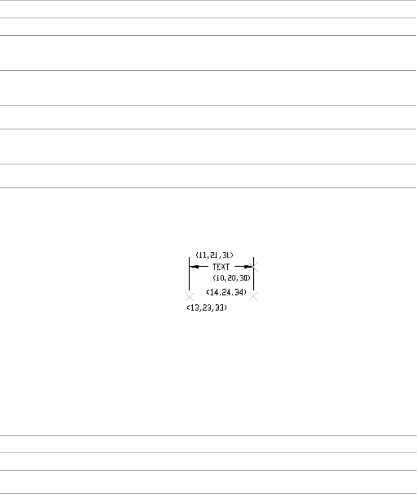
Aligned dimension group codes
DescriptionGroup code
DXF: Y and Z values of insertion point for clones of a dimension—Baseline and Continue (in
OCS)
22, 32
Definition point for linear and angular dimensions (in WCS)13
DXF: X value; APP: 3D point
DXF: Y and Z values of definition point for linear and angular dimensions (in WCS)23, 33
Definition point for linear and angular dimensions (in WCS)14
DXF: X value; APP: 3D point
DXF: Y and Z values of definition point for linear and angular dimensions (in WCS)24, 34
The point (13,23,33) specifies the start point of the first extension line and
the point (14,24,34) specifies the start point of the second extension line.
Point (10,20,30) specifies the dimension line location. The point (11,21,31)
specifies the midpoint of the dimension text.
Linear and Rotated Dimension Group Codes
The following group codes apply to linear and rotated dimensions (note that
linear and rotated dimensions are part of the AcDbAlignedDimension subclass).
In addition to the group codes described here, those listed in Common Group
Codes for Entities on page 61 and Common Dimension Group Codes on page
78 can also be present. For information about abbreviations and formatting
used in this table, see Formatting Conventions in This Reference on page 2.
Linear and rotated dimension group codes
DescriptionGroup code
Subclass marker (AcDbAlignedDimension)100
Insertion point for clones of a dimension—Baseline and Continue (in OCS)12
Linear and Rotated Dimension Group Codes | 81

Linear and rotated dimension group codes
DescriptionGroup code
DXF: X value; APP: 3D point
DXF: Y and Z values of insertion point for clones of a dimension—Baseline and Continue (in
OCS)
22, 32
Definition point for linear and angular dimensions (in WCS)13
DXF: X value; APP: 3D point
DXF: Y and Z values of definition point for linear and angular dimensions (in WCS)23, 33
Definition point for linear and angular dimensions (in WCS)14
DXF: X value; APP: 3D point
DXF: Y and Z values of definition point for linear and angular dimensions (in WCS)24, 34
Angle of rotated, horizontal, or vertical dimensions50
Linear dimension types with an oblique angle have an optional group code 52. When added
to the rotation angle of the linear dimension (group code 50), it gives the angle of the extension
lines
52
Subclass marker (AcDbRotatedDimension)100
Radial and Diameter Dimension Group Codes
The following group codes apply to radial and diameter dimensions. In
addition to the group codes described here, those listed in Common Group
Codes for Entities on page 61 and Common Dimension Group Codes on page
78 can also be present. For information about abbreviations and formatting
used in this table, see Formatting Conventions in This Reference on page 2.
Radial and diameter dimension group codes
DescriptionGroup code
Subclass marker (AcDbRadialDimension or AcDbDiametricDimension)100
Definition point for diameter, radius, and angular dimensions (in WCS)15
DXF: X value; APP: 3D point
82 | Chapter 6 ENTITIES Section
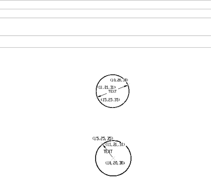
Radial and diameter dimension group codes
DescriptionGroup code
DXF: Y and Z values of definition point for diameter, radius, and angular dimensions (in
WCS)
25, 35
Leader length for radius and diameter dimensions40
The point (15,25,35) specifies the first point of the dimension line on the
circle/arc and the point (10,20,30) specifies the point opposite the first point.
The point (11,21,31) specifies the midpoint of the dimension text.
The point (15,25,35) specifies the first point of the dimension line on the
circle/arc and the point (10,20,30) specifies the center of the circle/arc. The
point (11,21,31) specifies the midpoint of the dimension text.
Angular Dimension Group Codes
The following group codes apply to angular dimensions. In addition to the
group codes described here, those listed in Common Group Codes for Entities
on page 61 and Common Dimension Group Codes on page 78 can also be
Angular Dimension Group Codes | 83
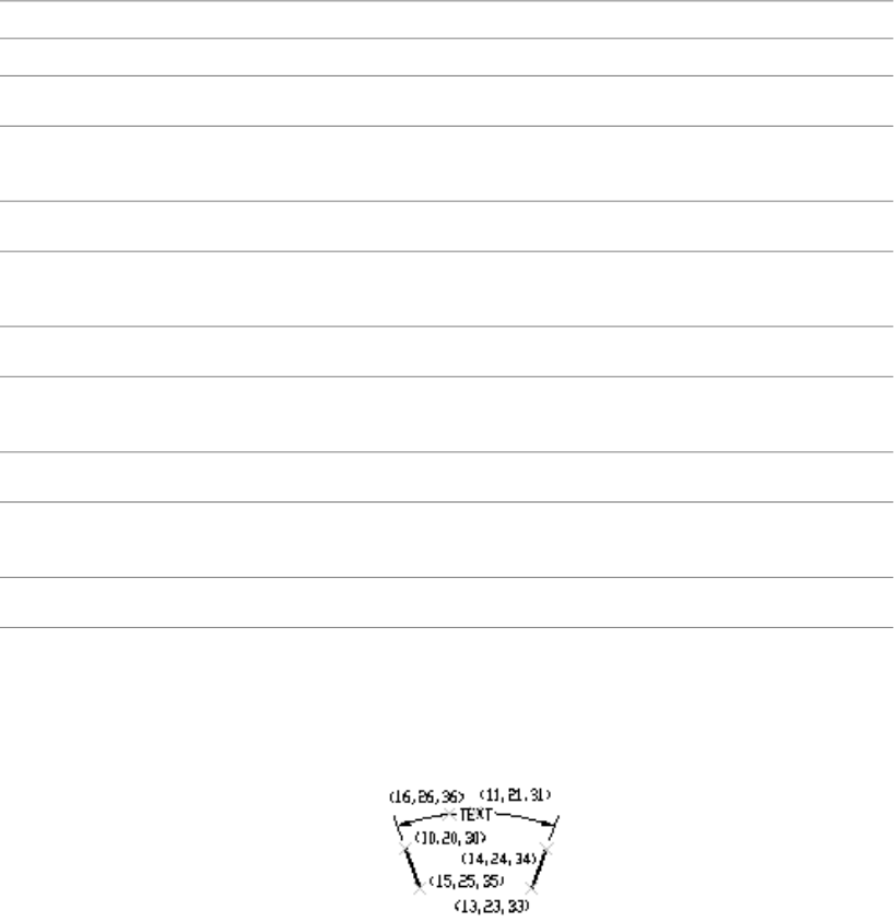
present. For information about abbreviations and formatting used in this table,
see Formatting Conventions in This Reference on page 2.
Angular dimension group codes
DescriptionGroup code
Subclass marker (AcDb3PointAngularDimension)100
Definition point for linear and angular dimensions (in WCS)13
DXF: X value; APP: 3D point
DXF: Y and Z values of definition point for linear and angular dimensions (in WCS)23, 33
Definition point for linear and angular dimensions (in WCS)14
DXF: X value; APP: 3D point
DXF: Y and Z values of definition point for linear and angular dimensions (in WCS)24, 34
Definition point for diameter, radius, and angular dimensions (in WCS) DXF: X value; APP: 3D
point
15
DXF: Y and Z values of definition point for diameter, radius, and angular dimensions (in WCS)25, 35
Point defining dimension arc for angular dimensions (in OCS)16
DXF: X value; APP: 3D point
DXF: Y and Z values of point defining dimension arc for angular dimensions (in OCS)26, 36
The points (13,23,33) and (14,24,34) specify the endpoints of the line used
to determine the first extension line. Points (10,20,30) and (15,25,35) specify
the endpoints of the line used to determine the second extension line. Point
(16,26,36) specifies the location of the dimension line arc. The point (11,21,31)
specifies the midpoint of the dimension text.
The point (15,25,35) specifies the vertex of the angle. The points (13,23,33)
and (14,24,34) specify the endpoints of the extension lines. The point
84 | Chapter 6 ENTITIES Section
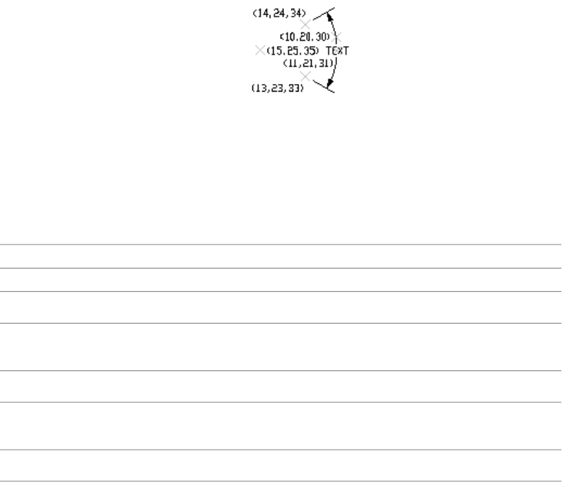
(10,20,30) specifies the location of the dimension line arc and the point
(11,21,31) specifies the midpoint of the dimension text.
Ordinate Dimension Group Codes
The following group codes apply to ordinate dimensions. In addition to the
group codes described here, those listed in Common Group Codes for Entities
on page 61 and Common Dimension Group Codes on page 78 can also be
present. For information about abbreviations and formatting used in this table,
see Formatting Conventions in This Reference on page 2.
Ordinate dimension group codes
DescriptionGroup code
Subclass marker (AcDbOrdinateDimension)100
Definition point for linear and angular dimensions (in WCS)13
DXF: X value; APP: 3D point
DXF: Y and Z values of definition point for linear and angular dimensions (in WCS)23, 33
Definition point for linear and angular dimensions (in WCS)14
DXF: X value; APP: 3D point
DXF: Y and Z values of definition point for linear and angular dimensions (in WCS)24, 34
The point (13,23,33) specifies the feature location and the point (14,24,34)
specifies the leader endpoint. The point (11,21,31) specifies the midpoint of
the dimension text. Point (10,20,30) is placed at the origin of the UCS that is
current when the dimension is created.
Ordinate Dimension Group Codes | 85
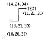
Dimension Style Overrides
Dimension style overrides can be applied to dimension, leader, and tolerance
entities. Any overrides applied to these entities are stored in the entity as
xdata. The overridden dimension variable group codes and the related values
are contained within group 1002 control strings. The following example shows
the xdata of a dimension entity where the DIMTOL and DIMCLRE variables
have been overridden.
(setq diment (car (entsel))) ; Select dimension entity
(setq elst (entget diment '("ACAD"))) ; Get entity definition list
(assoc -3 elst) ; Extract xdata only
This code returns the following:
(-3 ("ACAD" Start of the ACAD APPID section
of xdata
(1000 . "DSTYLE") (1002 . "{") Beginning of the dimstyle subsec
tion
(1070 . 177) (1070 . 3) The DIMCLRE (code 177) override +
value (3)
(1070 . 71) (1070 . 1) The DIMTOL (code 71) override +
value (1)
(1002 . "}") )) End dimstyle subsection and ACAD
section
ELLIPSE
The following group codes apply to ellipse entities. In addition to the group
codes described here, see Common Group Codes for Entities on page 61. For
86 | Chapter 6 ENTITIES Section

information about abbreviations and formatting used in this table, see
Formatting Conventions in This Reference on page 2.
Ellipse group codes
DescriptionGroup code
Subclass marker (AcDbEllipse)100
Center point (in WCS)10
DXF: X value; APP: 3D point
DXF: Y and Z values of center point (in WCS)20, 30
Endpoint of major axis, relative to the center (in WCS)11
DXF: X value; APP: 3D point
DXF: Y and Z values of endpoint of major axis, relative to the center (in WCS)21, 31
Extrusion direction (optional; default = 0, 0, 1)210
DXF: X value; APP: 3D vector
DXF: Y and Z values of extrusion direction (optional)220, 230
Ratio of minor axis to major axis40
Start parameter (this value is 0.0 for a full ellipse)41
End parameter (this value is 2pi for a full ellipse)42
HATCH
The following group codes apply to hatch and MPolygon entities. In addition
to the group codes described here, see Common Group Codes for Entities on
page 61. For information about abbreviations and formatting used in this
table, see Formatting Conventions in This Reference on page 2.
Hatch group codes
DescriptionGroup code
Subclass marker (AcDbHatch)100
Elevation point (in OCS)10
HATCH | 87

Hatch group codes
DescriptionGroup code
DXF: X value = 0; APP: 3D point (X and Y always equal 0, Z represents the elevation)
DXF: Y and Z values of elevation point (in OCS)20, 30
Y value = 0, Z represents the elevation
Extrusion direction (optional; default = 0, 0, 1)210
DXF: X value; APP: 3D vector
DXF: Y and Z values of extrusion direction220, 230
Hatch pattern name2
Solid fill flag (solid fill = 1; pattern fill = 0); for MPolygon, the version of MPolygon70
For MPolygon, pattern fill color as the ACI63
Associativity flag (associative = 1; non-associative = 0); for MPolygon, solid-fill flag (has solid
fill = 1; lacks solid fill = 0)
71
Number of boundary paths (loops)91
Boundary path data. Repeats number of times specified by code 91. See Boundary Path Data
on page 90
varies
Hatch style:75
0 = Hatch “odd parity” area (Normal style)
1 = Hatch outermost area only (Outer style)
2 = Hatch through entire area (Ignore style)
Hatch pattern type:76
0 = User-defined; 1 = Predefined; 2 = Custom
Hatch pattern angle (pattern fill only)52
Hatch pattern scale or spacing (pattern fill only)41
For MPolygon, boundary annotation flag (boundary is an annotated boundary = 1; boundary
is not an annotated boundary = 0)
73
Hatch pattern double flag (pattern fill only):77
88 | Chapter 6 ENTITIES Section
Hatch group codes
DescriptionGroup code
0 = not double; 1 = double
Number of pattern definition lines78
Pattern line data. Repeats number of times specified by code 78. See Pattern Data on page 94varies
Pixel size used to determine the density to perform various intersection and ray casting operations
in hatch pattern computation for associative hatches and hatches created with the Flood
method of hatching
47
Number of seed points98
For MPolygon, offset vector11
For MPolygon, number of degenerate boundary paths (loops), where a degenerate boundary
path is a border that is ignored by the hatch
99
Seed point (in OCS)10
DXF: X value; APP: 2D point (multiple entries)
DXF: Y value of seed point (in OCS); (multiple entries)20
Indicates solid hatch or gradient; if solid hatch, the values for the remaining codes are ignored
but must be present. Optional; if code 450 is in the file, then the following codes must be in
450
the file: 451, 452, 453, 460, 461, 462, and 470. If code 450 is not in the file, then the following
codes must not be in the file: 451, 452, 453, 460, 461, 462, and 470
0 = Solid hatch
1 = Gradient
Zero is reserved for future use451
Records how colors were defined and is used only by dialog code:452
0 = Two-color gradient
1 = Single-color gradient
Number of colors:453
0 = Solid hatch
2 = Gradient
Rotation angle in radians for gradients (default = 0, 0)460
HATCH | 89

Hatch group codes
DescriptionGroup code
Gradient definition; corresponds to the Centered option on the Gradient Tab of the Boundary
Hatch and Fill dialog box. Each gradient has two definitions, shifted and unshifted. A Shift value
461
describes the blend of the two definitions that should be used. A value of 0.0 means only the
unshifted version should be used, and a value of 1.0 means that only the shifted version should
be used.
Color tint value used by dialog code (default = 0, 0; range is 0.0 to 1.0). The color tint value is
a gradient color and controls the degree of tint in the dialog when the Hatch group code 452
is set to 1.
462
Reserved for future use:463
0 = First value
1 = Second value
String (default = LINEAR)470
Boundary Path Data
The boundary of each hatch object is defined by a path (or loop) that consists
of one or more segments. Path segment data varies depending on the entity
type (or types) that make up the path. Each path segment is defined by its
own set of group codes. For information about abbreviations and formatting
used in this table, see Formatting Conventions in This Reference on page 2.
Hatch boundary path data group codes
DescriptionGroup code
Boundary path type flag (bit coded):92
0 = Default; 1 = External; 2 = Polyline
4 = Derived; 8 = Textbox; 16 = Outermost
Polyline boundary type data (only if boundary = polyline). See Polyline boundary data table
below
varies
Number of edges in this boundary path (only if boundary is not a polyline)93
Edge type (only if boundary is not a polyline):72
1 = Line; 2 = Circular arc; 3 = Elliptic arc; 4 = Spline
90 | Chapter 6 ENTITIES Section
Hatch boundary path data group codes
DescriptionGroup code
Edge type data (only if boundary is not a polyline). See appropriate Edge data table belowvaries
Number of source boundary objects97
Reference to source boundary objects (multiple entries)330
Polyline boundary data group codes
DescriptionGroup code
Has bulge flag72
Is closed flag73
Number of polyline vertices93
Vertex location (in OCS)10
DXF: X value; APP: 2D point (multiple entries)
DXF: Y value of vertex location (in OCS) (multiple entries)20
Bulge (optional, default = 0)42
Line edge data group codes
DescriptionGroup code
Start point (in OCS)10
DXF: X value; APP: 2D point
DXF: Y value of start point (in OCS)20
Endpoint (in OCS)11
DXF: X value; APP: 2D point
Boundary Path Data | 91
Line edge data group codes
DescriptionGroup code
DXF: Y value of endpoint (in OCS)21
Arc edge data group codes
DescriptionGroup code
Center point (in OCS)10
DXF: X value; APP: 2D point
DXF: Y value of center point (in OCS)20
Radius40
Start angle50
End angle51
Is counterclockwise flag73
Ellipse edge data group codes
DescriptionGroup code
Center point (in OCS)10
DXF: X value; APP: 2D point
DXF: Y value of center point (in OCS)20
Endpoint of major axis relative to center point (in OCS)11
DXF: X value; APP: 2D point
DXF: Y value of endpoint of major axis (in OCS)21
Length of minor axis (percentage of major axis length)40
Start angle50
End angle51
92 | Chapter 6 ENTITIES Section
Ellipse edge data group codes
DescriptionGroup code
Is counterclockwise flag73
Spline edge data group codes
DescriptionGroup code
Degree94
Rational73
Periodic74
Number of knots95
Number of control points96
Knot values (multiple entries)40
Control point (in OCS)10
DXF: X value; APP: 2D point
DXF: Y value of control point (in OCS)20
Weights (optional, default = 1)42
Number of fit data97
Fit datum (in OCS)11
DXF: X value; APP: 2D point
DXF: Y value of fit datum (in OCS)21
Start tangent12
DXF: X value; APP: 2D vector
DXF: Y value of start tangent (in OCS)22
End tangent13
DXF: X value; APP: 2D vector
Boundary Path Data | 93
Spline edge data group codes
DescriptionGroup code
DXF: Y value of end tangent (in OCS)23
Pattern Data
The following pattern data codes repeat for each pattern definition line. For
information about abbreviations and formatting used in this table, see
Formatting Conventions in This Reference on page 2.
Hatch pattern data group codes
DescriptionGroup code
Pattern line angle53
Pattern line base point, X component43
Pattern line base point, Y component44
Pattern line offset, X component45
Pattern line offset, Y component46
Number of dash length items79
Dash length (multiple entries)49
HELIX
The following group codes apply to helix entities. In addition to the group
codes described here, see Common Group Codes for Entities on page 61. For
information about abbreviations and formatting used in this table, see
Formatting Conventions in This Reference on page 2.
Helix group codes
DescriptionGroup code
Spline data
94 | Chapter 6 ENTITIES Section
Helix group codes
DescriptionGroup code
Subclass marker (AcDbHelix)100
Major release number90
Maintainance release number91
Axis base point10, 20, 30
Start point11, 21, 31
Axis vector12, 22, 32
Radius40
Number of turns41
Turn height42
Handedness; 0 = left, 1 = right290
Constrain type280
0 = Constrain turn height
1 = Constrain turns
2 = Constrain height
IMAGE
The following group codes apply to image entities. In addition to the group
codes described here, see Common Group Codes for Entities on page 61. For
information about abbreviations and formatting used in this table, see
Formatting Conventions in This Reference on page 2.
Image group codes
DescriptionGroup code
Subclass marker (AcDbRasterImage)100
Class version90
IMAGE | 95

Image group codes
DescriptionGroup code
Insertion point (in WCS)10
DXF: X value; APP: 3D point
DXF: Y and Z values of insertion point (in WCS)20, 30
U-vector of a single pixel (points along the visual bottom of the image, starting at the insertion
point) (in WCS)
11
DXF: X value; APP: 3D point
DXF: Y and Z values U-vector (in WCS)21, 31
V-vector of a single pixel (points along the visual left side of the image, starting at the insertion
point) (in WCS)
12
DXF: X value; APP: 3D point
DXF: Y and Z values of V-vector (in WCS)22, 32
Image size in pixels13
DXF: U value; APP: 2D point (U and V values)
DXF: V value of image size in pixels23
Hard reference to imagedef object340
Image display properties:70
1 = Show image
2 = Show image when not aligned with screen
4 = Use clipping boundary
8 = Transparency is on
Clipping state: 0 = Off; 1 = On280
Brightness value (0-100; default = 50)281
Contrast value (0-100; default = 50)282
Fade value (0-100; default = 0)283
Hard reference to imagedef_reactor object360
96 | Chapter 6 ENTITIES Section
Image group codes
DescriptionGroup code
Clipping boundary type. 1 = Rectangular; 2 = Polygonal71
Number of clip boundary vertices that follow91
Clip boundary vertex (in OCS)14
DXF: X value; APP: 2D point (multiple entries)
NOTE 1) For rectangular clip boundary type, two opposite corners must be specified. Default
is (-0.5,-0.5), (size.x-0.5, size.y-0.5). 2) For polygonal clip boundary type, three or more vertices
must be specified. Polygonal vertices must be listed sequentially
DXF: Y value of clip boundary vertex (in OCS) (multiple entries)24
Clip Mode: 0 = Outside Mode; 1 = Inside Mode290
INSERT
The following group codes apply to insert (block reference) entities. In addition
to the group codes described here, see Common Group Codes for Entities on
page 61. For information about abbreviations and formatting used in this
table, see Formatting Conventions in This Reference on page 2.
Insert group codes
DescriptionGroup code
Subclass marker (AcDbBlockReference)100
Variable attributes-follow flag (optional; default = 0); if the value of attributes-follow flag is 1,
a series of attribute entities is expected to follow the insert, terminated by a seqend entity
66
Block name2
Insertion point (in OCS)10
DXF: X value; APP: 3D point
DXF: Y and Z values of insertion point (in OCS)20, 30
X scale factor (optional; default = 1)41
Y scale factor (optional; default = 1)42
INSERT | 97
Insert group codes
DescriptionGroup code
Z scale factor (optional; default = 1)43
Rotation angle (optional; default = 0)50
Column count (optional; default = 1)70
Row count (optional; default = 1)71
Column spacing (optional; default = 0)44
Row spacing (optional; default = 0)45
Extrusion direction (optional; default = 0, 0, 1)210
DXF: X value; APP: 3D vector
DXF: Y and Z values of extrusion direction (optional)220, 230
LEADER
The following group codes apply to leader entities. In addition to the group
codes described here, see Common Group Codes for Entities on page 61. For
information about abbreviations and formatting used in this table, see
Formatting Conventions in This Reference on page 2.
Leader group codes
DescriptionGroup code
Subclass marker (AcDbLeader)100
Dimension style name3
Arrowhead flag: 0 = Disabled; 1 = Enabled71
Leader path type: 0 = Straight line segments; 1 = Spline72
Leader creation flag (default = 3):73
0 = Created with text annotation
1 = Created with tolerance annotation
2 = Created with block reference annotation
98 | Chapter 6 ENTITIES Section
Leader group codes
DescriptionGroup code
3 = Created without any annotation
Hookline direction flag:74
0 = Hookline (or end of tangent for a splined leader) is the opposite direction from the horizontal
vector
1 = Hookline (or end of tangent for a splined leader) is the same direction as horizontal vector
(see code 75)
Hookline flag: 0 = No hookline; 1 = Has a hookline75
Text annotation height40
Text annotation width41
Number of vertices in leader (ignored for OPEN)76
Vertex coordinates (one entry for each vertex)10
DXF: X value; APP: 3D point
DXF: Y and Z values of vertex coordinates20, 30
Color to use if leader's DIMCLRD = BYBLOCK77
Hard reference to associated annotation (mtext, tolerance, or insert entity)340
Normal vector210
DXF: X value; APP: 3D vector
DXF: Y and Z values of normal vector220, 230
“Horizontal” direction for leader211
DXF: X value; APP: 3D vector
DXF: Y and Z values of “horizontal” direction for leader221, 231
Offset of last leader vertex from block reference insertion point212
DXF: X value; APP: 3D vector
DXF: Y and Z values of offset222, 232
LEADER | 99
Leader group codes
DescriptionGroup code
Offset of last leader vertex from annotation placement point213
DXF: X value; APP: 3D vector
DXF: Y and Z values of offset223, 233
Xdata belonging to the application ID "ACAD" follows a leader entity if any
dimension overrides have been applied to this entity. See Dimension Style
Overrides on page 86.
LIGHT
The following group codes apply to light entities. In addition to the group
codes described here, see Common Group Codes for Entities on page 61. For
information about abbreviations and formatting used in this table, see
Formatting Conventions in This Reference on page 2.
Light group codes
DescriptionGroup code
Subclass marker (AcDbLight)100
Version number90
Light name1
Light type (distant = 1; point = 2; spot = 3)70
Status290
Plot glyph291
Intensity40
Light Position10
DXF: X value; APP: 3D point
DXF: X, Y, and Z values of the light position20, 30
Target location11
100 | Chapter 6 ENTITIES Section
Light group codes
DescriptionGroup code
DXF: X value; APP: 3D point
DXF: X, Y, and Z values of the target location21, 31
Attenuation type72
0 = None
1 = Inverse Linear
2 = Inverse Square
Use attenuation limits292
Attenuation start limit41
Attenuation end limit42
Hotspot angle50
Falloff angle51
Cast shadows293
Shadow Type73
0 = Ray traced shadows
1 = Shadow maps
Shadow map size91
Shadow map softness280
LINE
The following group codes apply to line entities. In addition to the group
codes described here, see Common Group Codes for Entities on page 61. For
LINE | 101
information about abbreviations and formatting used in this table, see
Formatting Conventions in This Reference on page 2.
Line group codes
DescriptionGroup code
Subclass marker (AcDbLine)100
Thickness (optional; default = 0)39
Start point (in WCS)10
DXF: X value; APP: 3D point
DXF: Y and Z values of start point (in WCS)20, 30
Endpoint (in WCS)11
DXF: X value; APP: 3D point
DXF: Y and Z values of endpoint (in WCS)21, 31
Extrusion direction (optional; default = 0, 0, 1)210
DXF: X value; APP: 3D vector
DXF: Y and Z values of extrusion direction (optional)220, 230
LWPOLYLINE
The following group codes apply to lwpolyline entities. In addition to the
group codes described here, see Common Group Codes for Entities on page
61. For information about abbreviations and formatting used in this table,
see Formatting Conventions in This Reference on page 2.
Lwpolyline group codes
DescriptionGroup code
Subclass marker (AcDbPolyline)100
Number of vertices90
Polyline flag (bit-coded); default is 0:70
1 = Closed; 128 = Plinegen
102 | Chapter 6 ENTITIES Section
Lwpolyline group codes
DescriptionGroup code
Constant width (optional; default = 0). Not used if variable width (codes 40 and/or 41) is set43
Elevation (optional; default = 0)38
Thickness (optional; default = 0)39
Vertex coordinates (in OCS), multiple entries; one entry for each vertex10
DXF: X value; APP: 2D point
DXF: Y value of vertex coordinates (in OCS), multiple entries; one entry for each vertex20
Vertex identifier91
Starting width (multiple entries; one entry for each vertex) (optional; default = 0; multiple
entries). Not used if constant width (code 43) is set
40
End width (multiple entries; one entry for each vertex) (optional; default = 0; multiple entries).
Not used if constant width (code 43) is set
41
Bulge (multiple entries; one entry for each vertex) (optional; default = 0)42
Extrusion direction (optional; default = 0, 0, 1)210
DXF: X value; APP: 3D vector
DXF: Y and Z values of extrusion direction (optional)220, 230
MESH
The following group codes apply to the mesh entity. In addition to the group
codes described here, see Common Group Codes for Entities on page 61. For
information about abbreviations and formatting used in this table, see
Formatting Conventions in This Reference on page 2.
Mesh group codes
DescriptionGroup code
Subclass marker (AcDbSubDMesh)100
Version number71
MESH | 103
Mesh group codes
DescriptionGroup code
"Blend Crease" property72
0 = Turn off
1 = Turn on
Number of subdivision level91
Vertex count of level 092
Vertex position10
Size of face list of level 093
Face list item90
Edge count of level 094
Vertex index of each edge90
Edge crease count of level 095
Edge create value140
Count of sub-entity which property has been overridden90
Sub-entity marker91
Count of property was overridden92
Property type90
0 = Color
1 = Material
2 = Transparency
3 = Material mapper
MLINE
The following group codes apply to mline entities. In addition to the group
codes described here, see Common Group Codes for Entities on page 61. For
104 | Chapter 6 ENTITIES Section
information about abbreviations and formatting used in this table, see
Formatting Conventions in This Reference on page 2.
Mline group codes
DescriptionGroup code
Subclass marker (AcDbMline)100
String of up to 32 characters. The name of the style used for this mline. An entry for this style
must exist in the MLINESTYLE dictionary.
2
Do not modify this field without also updating the associated entry in the MLINESTYLE dictionary
Pointer-handle/ID of MLINESTYLE object340
Scale factor40
Justification: 0 = Top; 1 = Zero; 2 = Bottom70
Flags (bit-coded values):71
1 = Has at least one vertex (code 72 is greater than 0)
2 = Closed
4 = Suppress start caps
8 = Suppress end caps
Number of vertices72
Number of elements in MLINESTYLE definition73
Start point (in WCS)10
DXF: X value; APP: 3D point
DXF: Y and Z values of start point (in WCS)20, 30
Extrusion direction (optional; default = 0, 0, 1)210
DXF: X value; APP: 3D vector
DXF: Y and Z values of extrusion direction (optional)220, 230
Vertex coordinates (multiple entries; one entry for each vertex) DXF: X value; APP: 3D point11
DXF: Y and Z values of vertex coordinates21, 31
Direction vector of segment starting at this vertex (multiple entries; one for each vertex)12
MLINE | 105
Mline group codes
DescriptionGroup code
DXF: X value; APP: 3D vector
DXF: Y and Z values of direction vector of segment starting at this vertex22, 32
Direction vector of miter at this vertex (multiple entries: one for each vertex)13
DXF: X value; APP: 3D vector
DXF: Y and Z values of direction vector of miter23, 33
Number of parameters for this element (repeats for each element in segment)74
Element parameters (repeats based on previous code 74)41
Number of area fill parameters for this element (repeats for each element in segment)75
Area fill parameters (repeats based on previous code 75)42
The group code 41 parameterization is a list of real values, one real per group
code 41. The list may contain zero or more items. The first group code 41
value is the distance from the segment vertex along the miter vector to the
point where the line element's path intersects the miter vector. The next group
code 41 value is the distance along the line element's path from the point
defined by the first group 41 to the actual start of the line element. The next
is the distance from the start of the line element to the first break (or cut) in
the line element. The successive group code 41 values continue to list the start
and stop points of the line element in this segment of the mline. Linetypes
do not affect group 41 lists.
The group code 42 parameterization is also a list of real values. Similar to the
41 parameterization, it describes the parameterization of the fill area for this
mline segment. The values are interpreted identically to the 41 parameters
and when taken as a whole for all line elements in the mline segment, they
define the boundary of the fill area for the mline segment.
A common example of the use of the group code 42 mechanism is when an
unfilled mline crosses over a filled mline and mledit is used to cause the filled
mline to appear unfilled in the crossing area. This would result in two group
42s for each line element in the affected mline segment; one for the fill stop
and one for the fill start.
106 | Chapter 6 ENTITIES Section
The 2 group codes in mline entities and mlinestyle objects are redundant
fields. These groups should not be modified under any circumstances, although
it is safe to read them and use their values. The correct fields to modify are as
follows:
Mline The 340 group in the same object, which indicates the proper
MLINESTYLE object.
Mlinestyle The 3 group value in the MLINESTYLE dictionary, which precedes
the 350 group that has the handle or entity name of the current mlinestyle.
MLEADERSTYLE
The following group codes apply to mleaderstyle entities. In addition to the
group codes described here, see Common Group Codes for Entities on page
61. For information about abbreviations and formatting used in this table,
see Formatting Conventions in This Reference on page 2.
MLeaderstyle group codes
DescriptionGroup code
Content Type170
DrawMLeaderOrder Type171
DrawLeaderOrder Type172
MaxLeader Segments Points90
First Segment Angle Constraint40
Second Segment Angle Constraint41
LeaderLineType173
LeaderLineColor91
LeaderLineType ID340
LeaderLineWeight92
Enable Landing290
MLEADERSTYLE | 107

MLeaderstyle group codes
DescriptionGroup code
Landing Gap42
Enable Dogleg291
Dogleg Length43
Mleader Style Description3
Arrowhead ID341
Arrowhead Size44
Default MText Contents300
mTextStyleId342
Text Left Attachment Type174
Text Angle Type175
Text Alignment Type176
Text Right Attachment Type178
Text Color93
Text Height45
Enable Frame Text292
Text Align Always Left297
Align Space46
Block Content ID343
Block Content Color94
Block Content Scale on X-axis47
108 | Chapter 6 ENTITIES Section

MLeaderstyle group codes
DescriptionGroup code
Block Content Scale on Y-axis49
Block Content Scale on Z-axis140
Enable Block Content Scale293
Block Content Rotation141
Enable Block Content Rotation294
Block Content Connection Type177
Scale142
Overwrite Property Value295
Is Annotative296
Break Gap Size143
Text attachment direction for MText contents:271
0 = Horizontal
1 = Vertical
Bottom text attachment direction:272
9 = Center
10 = Underline and Center
Top text attachment direction:273
9 = Center
10 = Overline and Center
MLEADER
MLeader entity definitions consist of group codes that are common to all
MLeader types, followed by codes specific to the type.
MLEADER | 109
Common MLeader Group Codes
The following group codes apply to all mleaderstyle entity types. In addition
to the group codes described here, see Common Group Codes for Entities on
page 61. For information about abbreviations and formatting used in this
table, see Formatting Conventions in This Reference on page 2.
Common MLeader Line Group Codes
DescriptionGroup code
Leader Style Id340
Property Override Flag90
LeaderLineType170
Leade LineColor91
LeaderLineTypeID341
LeaderLine Weight171
Enable Landing290
Enable Dogleg291
Dogleg Length41
Arrowhead ID342
Arrowhead Size42
Content Type172
Text Style ID343
Text Left Attachment Type173
Text Right Attachement Type95
Text Angle Type174
Text Alignment Type175
110 | Chapter 6 ENTITIES Section
Common MLeader Line Group Codes
DescriptionGroup code
Text Color92
Enable Frame Text292
Block Content ID344
Block Content Color93
Block Content Scale10
Block Content Rotation43
Block Content Connection Type176
Enable Annotation Scale293
Arrowhead Index94
Arrowhead ID345
Block AttributerId330
Block Attribute Index177
Block Attribute Width44
Block Attribute Text String302
Text Direction Negative294
Text Align in IPE178
Text Attachment Point179
Text attachment direction for MText con-
tents:
271
0 = Horizontal
1 = Vertical
Bottom text attachment direction:272
Common MLeader Group Codes | 111
Common MLeader Line Group Codes
DescriptionGroup code
9 = Center
10 = Underline and Center
Top text attachment direction:273
9 = Center
10 = Overline and Center
MLeader Context Data Group Codes
The following group codes apply to all mleader entity types’ context data. In
addition to the group codes described here, see Common Group Codes for
Entities on page 61. For information about abbreviations and formatting used
in this table, see Formatting Conventions in This Reference on page 2.
MLeader Context Data group codes
DescriptionGroup code
Content Scale40
Content Base Position10,20,30
Text Height41
Arrowhead Size140
Landing Gap145
hasMText290
Default Text Contents304
Text Normal Direction11,21,31
Text Style ID340
Text Location12,22,32
Text Direction13,23,33
112 | Chapter 6 ENTITIES Section

MLeader Context Data group codes
DescriptionGroup code
Text Rotation42
Text Width43
Text Height44
Text Line Spacing Factor45
Text Line Spacing Style170
Text Color90
Text Attachment171
Text Flow Direction172
Text Background Color91
Text Background Scale Factor141
Text Background Transparency92
Is Text Background Color On291
Is Text Background Fill On292
Text Column Type173
Use Text Auto Height293
Text Column Width142
Text Column Gutter Width143
Text Column Flow Reversed294
Text Column Height144
Text Use Word Break295
MLeader Context Data Group Codes | 113

MLeader Context Data group codes
DescriptionGroup code
HasBlock296
Block Content ID341
Block Content Normal Direction14,24,34
Block Content Position15,25,35
Block Content Scale16
Block Content Rotation46
Block Content Color93
Block Transformation Matrix47
MLeader Plane Origin Point110
MLeader Plane X-Axis Direction111
MLeader Plane Y-Axis Direction112
MLeader Plane Normal Reversed297
Vertex10,20,30
Break Point Index90
Text Width43
Text Height44
Text Line Spacing Factor45
Text Line Spacing Style170
Text Color90
Text Attachment171
114 | Chapter 6 ENTITIES Section

MLeader Context Data group codes
DescriptionGroup code
Text Flow Direction172
Text Background Color91
Text Background Scale Factor141
Text Background Transparency92
Is Text Background Color On291
Is Text Background Fill On292
Text Column Type173
Use Text Auto Height293
Text Column Width142
Text Column Gutter Width143
Text Column Flow Reversed294
Text Column Height144
Text Use Word Break295
HasBlock296
Block Content ID341
Block Content Normal Direction14,24,34
Block Content Position15,25,35
Block Content Scale16
Block Content Rotation46
BLock Content Color93
MLeader Context Data Group Codes | 115
MLeader Context Data group codes
DescriptionGroup code
BLock Transformation Matrix47
Mleader Plane Origin Point110
MLeader Plane X-Axis Direction111
MLeader Plane Y-Axis Direction112
MLeader Plane Normal Reversed297
MLeader Leader Node Group Codes
The following group codes apply to all mleader entity types’ leader node. In
addition to the group codes described here, see Common Group Codes for
Entities on page 61. For information about abbreviations and formatting used
in this table, see Formatting Conventions in This Reference on page 2.
MLeader Leader Node Group Codes
DescriptionGroup code
Has Set Last Leader Line Point290
Has Set Dogleg Vector291
Last Leader Line Point10,20,30
Dogleg Vector11,21,31
Break Start Point12,22,32
Break End Point13,23,33
Leader Branch Index90
Dogleg Length40
116 | Chapter 6 ENTITIES Section
MLeader Leader Line Group Codes
The following group codes apply to all mleader entity types’ leader line. In
addition to the group codes described here, see Common Group Codes for
Entities on page 61. For information about abbreviations and formatting used
in this table, see Formatting Conventions in This Reference on page 2.
Leader Line Group Codes
DescriptionGroup code
Vertex10,20,30
Break Point Index90
Break Start Point11,21,31
Break End Point12,22,32
Leader Line Index91
MTEXT
The following group codes apply to mtext entities. In addition to the group
codes described here, see Common Group Codes for Entities on page 61. For
information about abbreviations and formatting used in this table, see
Formatting Conventions in This Reference on page 2.
Mtext group codes
DescriptionGroup code
Subclass marker (AcDbMText)100
Insertion point10
DXF: X value; APP: 3D point
DXF: Y and Z values of insertion point20, 30
Nominal (initial) text height40
Reference rectangle width41
Attachment point:71
MLeader Leader Line Group Codes | 117
Mtext group codes
DescriptionGroup code
1 = Top left; 2 = Top center; 3 = Top right
4 = Middle left; 5 = Middle center; 6 = Middle right
7 = Bottom left; 8 = Bottom center; 9 = Bottom right
Drawing direction:72
1 = Left to right
3 = Top to bottom
5 = By style (the flow direction is inherited from the associated text style)
Text string. If the text string is less than 250 characters, all characters appear in group 1. If the
text string is greater than 250 characters, the string is divided into 250-character chunks, which
1
appear in one or more group 3 codes. If group 3 codes are used, the last group is a group 1
and has fewer than 250 characters
Additional text (always in 250-character chunks) (optional)3
Text style name (STANDARD if not provided) (optional)7
Extrusion direction (optional; default = 0, 0, 1)210
DXF: X value; APP: 3D vector
DXF: Y and Z values of extrusion direction (optional)220, 230
X-axis direction vector (in WCS)11
DXF: X value; APP: 3D vector
A group code 50 (rotation angle in radians) passed as DXF input is converted to the equivalent
direction vector (if both a code 50 and codes 11, 21, 31 are passed, the last one wins). This is
provided as a convenience for conversions from text objects
DXF: Y and Z values of X-axis direction vector (in WCS)21, 31
Horizontal width of the characters that make up the mtext entity. This value will always be
equal to or less than the value of group code 41 (read-only, ignored if supplied)
42
Vertical height of the mtext entity (read-only, ignored if supplied)43
Rotation angle in radians50
Mtext line spacing style (optional):73
1 = At least (taller characters will override)
118 | Chapter 6 ENTITIES Section
Mtext group codes
DescriptionGroup code
2 = Exact (taller characters will not override)
Mtext line spacing factor (optional):44
Percentage of default (3-on-5) line spacing to be applied. Valid values range from 0.25 to 4.00
Background fill setting:90
0 = Background fill off
1 = Use background fill color
2 = Use drawing window color as background fill color
Background color (if RGB color)420 - 429
Background color (if color name)430 - 439
Fill box scale (optional):45
Determines how much border there is around the text.
Background fill color (optional):63
Color to use for background fill when group code 90 is 1.
Transparency of background fill color (not implemented)441
Column type75
Column count76
Column Flow Reversed78
Column Autoheight79
Column width48
Column gutter49
Column heights; this code is followed by a column count (Int16), and then the number of
column heights
50
Xdata with the "DCO15" application ID may follow an mtext entity. This
contains information related to the dbConnect feature.
MTEXT | 119

OLEFRAME
The following group codes apply to oleframe entities. In addition to the group
codes described here, see Common Group Codes for Entities on page 61. For
information about abbreviations and formatting used in this table, see
Formatting Conventions in This Reference on page 2.
Oleframe group codes
DescriptionGroup code
Subclass marker (AcDbOleFrame)100
OLE version number70
Length of binary data90
Binary data (multiple lines)310
End of OLE data (the string “OLE”)1
OLE2FRAME
The following group codes apply to ole2frame entities. This information is
read-only. During OPEN, the values are ignored because they are part of the
OLE binary object, and are obtained by access functions. In addition to the
group codes described here, see Common Group Codes for Entities on page
61. For information about abbreviations and formatting used in this table,
see Formatting Conventions in This Reference on page 2.
Ole2frame group codes
DescriptionGroup code
Subclass marker (AcDbOle2Frame)100
OLE version number70
Length of binary data3
Upper-left corner (WCS)10
DXF: X value; APP: 3D point
DXF: Y and Z values of upper-left corner (in WCS)20, 30
120 | Chapter 6 ENTITIES Section
Ole2frame group codes
DescriptionGroup code
Lower-right corner (WCS)11
DXF: X value; APP: 3D point
DXF: Y and Z values of lower-right corner (in WCS)21, 31
OLE object type, 1 = Link; 2 = Embedded; 3 = Static71
Tile mode descriptor:72
0 = Object resides in model space
1 = Object resides in paper space
Length of binary data90
Binary data (multiple lines)310
End of OLE data (the string “OLE”)1
OLE2FRAME | 121
Sample DXF output:
OLE2FRAME
5
2D
100
AcDbEntity
67
1
8
0
100
AcDbOle2Frame
70
2
3
Paintbrush Picture
10
4.43116
20
5.665992
30
0.0
11
6.4188
21
4.244939
31
0.0
71
2
72
1
90
23680
310
0155764BD60082B91140114B08C8F9A916400000000000000000506DC0D0D9AC
310
1940114B08C8F9A916400000000000000000506DC0D0D9AC194002303E5CD1FA
310
10400000000000000000764BD60082B9114002303E5CD1FA1040000000000000
...
...
122 | Chapter 6 ENTITIES Section

AutoLISP entnext function sample output:
Command: (setq e (entget e3))
((-1 . <Entity name: 7d50428>) (0 . "OLE2FRAME") (5 . "2D")
(100 . "AcDbEntity") (67 . 1) (8 . "0") (100 . "AcDbOle2Frame")
(70 . 2) (3 "Paintbrush Picture") (10 4.43116 5.66599 0.0)
(11 6.4188 4.24494 0.0) (71 . 2) (72 . 1))
POINT
The following group codes apply to point entities. In addition to the group
codes described here, see Common Group Codes for Entities on page 61. For
information about abbreviations and formatting used in this table, see
Formatting Conventions in This Reference on page 2.
Point group codes
DescriptionGroup code
Subclass marker (AcDbPoint)100
Point location (in WCS)10
DXF: X value; APP: 3D point
DXF: Y and Z values of point location (in WCS)20, 30
Thickness (optional; default = 0)39
Extrusion direction (optional; default = 0, 0, 1)210
DXF: X value; APP: 3D vector
DXF: Y and Z values of extrusion direction (optional)220, 230
Angle of the X axis for the UCS in effect when the point was drawn (optional, default = 0); used
when PDMODE is nonzero
50
POLYLINE
The following group codes apply to polyline entities. In addition to the group
codes described here, see Common Group Codes for Entities on page 61. For
POINT | 123

information about abbreviations and formatting used in this table, see
Formatting Conventions in This Reference on page 2.
Polyline group codes
DescriptionGroup code
Subclass marker (AcDb2dPolyline or AcDb3dPolyline)100
Obsolete; formerly an “entities follow flag” (optional; ignore if present)66
DXF: always 010
APP: a “dummy” point; the X and Y values are always 0, and the Z value is the polyline's
elevation (in OCS when 2D, WCS when 3D)
DXF: always 020
DXF: polyline's elevation (in OCS when 2D; WCS when 3D)30
Thickness (optional; default = 0)39
Polyline flag (bit-coded; default = 0):70
1 = This is a closed polyline (or a polygon mesh closed in the M direction)
2 = Curve-fit vertices have been added
4 = Spline-fit vertices have been added
8 = This is a 3D polyline
16 = This is a 3D polygon mesh
32 = The polygon mesh is closed in the N direction
64 = The polyline is a polyface mesh
128 = The linetype pattern is generated continuously around the vertices of this polyline
Default start width (optional; default = 0)40
Default end width (optional; default = 0)41
Polygon mesh M vertex count (optional; default = 0)71
Polygon mesh N vertex count (optional; default = 0)72
Smooth surface M density (optional; default = 0)73
Smooth surface N density (optional; default = 0)74
Curves and smooth surface type (optional; default = 0); integer codes, not bit-coded:75
124 | Chapter 6 ENTITIES Section

Polyline group codes
DescriptionGroup code
0 = No smooth surface fitted
5 = Quadratic B-spline surface
6 = Cubic B-spline surface
8 = Bezier surface
Extrusion direction (optional; default = 0, 0, 1)210
DXF: X value; APP: 3D vector
DXF: Y and Z values of extrusion direction (optional)220, 230
Xdata with the "AUTOCAD_POSTSCRIPT_FIGURE" application ID may follow a
polyline entity. This contains information related to PostScript images and
PostScript fill information.
Polyface Meshes
A polyface mesh is represented in DXF as a variant of a polyline entity. The
polyline header is identified as introducing a polyface mesh by the presence
of the 64 bit in the polyline flags (70) group. The 71 group specifies the number
of vertices in the mesh, and the 72 group specifies the number of faces.
Although these counts are correct for all meshes created with the PFACE
command, applications are not required to place correct values in these fields.
Following the polyline header is a sequence of vertex entities that specify the
vertex coordinates, followed by faces that compose the mesh.
The AutoCAD entity structure imposes a limit on the number of vertices that
a given face entity can specify. You can represent more complex polygons by
decomposing them into triangular wedges. Their edges should be made
invisible to prevent visible artifacts of this subdivision from being drawn. The
PFACE command performs this subdivision automatically, but when
applications generate polyface meshes directly, the applications must do this
themselves. The number of vertices per face is the key parameter in this
subdivision process. The PFACEVMAX system variable provides an application
with the number of vertices per face entity. This value is read-only and is set
to 4.
Polyface meshes created with the PFACE command are always generated with
all the vertex coordinate entities first, followed by the face definition entities.
The code within AutoCAD that processes polyface meshes requires this
ordering. Programs that generate polyface meshes in DXF should generate all
Polyface Meshes | 125
the vertices, and then all the faces. However, programs that read polyface
meshes from DXF should be tolerant of odd vertex and face ordering.
RAY
The following group codes apply to ray entities. In addition to the group codes
described here, see Common Group Codes for Entities on page 61. For
information about abbreviations and formatting used in this table, see
Formatting Conventions in This Reference on page 2.
Ray group codes
DescriptionGroup code
Subclass marker (AcDbRay)100
Start point (in WCS)10
DXF: X value; APP: 3D point
DXF: Y and Z values of start point (in WCS)20, 30
Unit direction vector (in WCS)11
DXF: X value; APP: 3D vector
DXF: Y and Z values of unit direction vector (in WCS)21, 31
REGION
The following group codes apply to region entities. In addition to the group
codes described here, see Common Group Codes for Entities on page 61. For
information about abbreviations and formatting used in this table, see
Formatting Conventions in This Reference on page 2.
Region group codes
DescriptionGroup code
Subclass marker (AcDbModelerGeometry)100
Modeler format version number (currently = 1)70
Proprietary data (multiple lines < 255 characters each)1
126 | Chapter 6 ENTITIES Section

Region group codes
DescriptionGroup code
Additional lines of proprietary data (if previous group 1 string is greater than 255 characters)
(optional)
3
SECTION
The following group codes apply to section entities. In addition to the group
codes described here, see Common Group Codes for Entities on page 61. For
information about abbreviations and formatting used in this table, see
Formatting Conventions in This Reference on page 2.
Section group codes
DescriptionGroup code
Subclass marker (AcDbSection)100
Section state90
Section flags91
Name1
Vertical direction10, 20, 30
Top height40
Bottom height41
Indicator transparency70
Indicator color63, 411
Number of vertices92
Vertex (repeats for number of vertices)11, 21, 31
Number of back line vertices93
Back line vertex (repeats for number of back line vertices)12, 22, 32
SECTION | 127

Section group codes
DescriptionGroup code
Hard-pointer ID/handle to geometry settings object360
SEQEND
The following group codes apply to seqend entities. In addition to the group
codes described here, see Common Group Codes for Entities on page 61. For
information about abbreviations and formatting used in this table, see
Formatting Conventions in This Reference on page 2.
Seqend group codes
DescriptionGroup code
APP: name of entity that began the sequence. This entity marks the end of vertex (vertex
type name) for a polyline, or the end of attribute entities (attrib type name) for an insert
-2
entity that has attributes (indicated by 66 group present and nonzero in insert entity).
This code is not saved in a DXF file
SHAPE
The following group codes apply to shape entities. In addition to the group
codes described here, see Common Group Codes for Entities on page 61. For
information about abbreviations and formatting used in this table, see
Formatting Conventions in This Reference on page 2.
Shape group codes
DescriptionGroup code
Subclass marker (AcDbShape)100
Thickness (optional; default = 0)39
Insertion point (in WCS)10
DXF: X value; APP: 3D point
DXF: Y and Z values of insertion point (in WCS)20, 30
Size40
128 | Chapter 6 ENTITIES Section

Shape group codes
DescriptionGroup code
Shape name2
Rotation angle (optional; default = 0)50
Relative X scale factor (optional; default = 1)41
Oblique angle (optional; default = 0)51
Extrusion direction (optional; default = 0, 0, 1)210
DXF: X value; APP: 3D vector
DXF: Y and Z values of extrusion direction (optional)220, 230
SOLID
The following group codes apply to solid entities. In addition to the group
codes described here, see Common Group Codes for Entities on page 61. For
information about abbreviations and formatting used in this table, see
Formatting Conventions in This Reference on page 2.
Solid group codes
DescriptionGroup code
Subclass marker (AcDbTrace)100
First corner10
DXF: X value; APP: 3D point
DXF: Y and Z values of first corner20, 30
Second corner11
DXF: X value; APP: 3D point
DXF: Y and Z values of second corner21, 31
Third corner12
XF: X value; APP: 3D point
DXF: Y and Z values of third corner22, 32
SOLID | 129
Solid group codes
DescriptionGroup code
Fourth corner. If only three corners are entered to define the SOLID, then the fourth corner
coordinate is the same as the third.
13
DXF: X value; APP: 3D point
DXF: Y and Z values of fourth corner23, 33
Thickness (optional; default = 0)39
Extrusion direction (optional; default = 0, 0, 1)210
DXF: X value; APP: 3D vector
DXF: Y and Z values of extrusion direction (optional)220, 230
SPLINE
The following group codes apply to spline entities. In addition to the group
codes described here, see Common Group Codes for Entities on page 61. For
information about abbreviations and formatting used in this table, see
Formatting Conventions in This Reference on page 2.
Spline group codes
DescriptionGroup code
Subclass marker (AcDbSpline)100
Normal vector (omitted if the spline is nonplanar)210
DXF: X value; APP: 3D vector
DXF: Y and Z values of normal vector (optional)220, 230
Spline flag (bit coded):70
1 = Closed spline
2 = Periodic spline
4 = Rational spline
8 = Planar
16 = Linear (planar bit is also set)
Degree of the spline curve71
130 | Chapter 6 ENTITIES Section
Spline group codes
DescriptionGroup code
Number of knots72
Number of control points73
Number of fit points (if any)74
Knot tolerance (default = 0.0000001)42
Control-point tolerance (default = 0.0000001)43
Fit tolerance (default = 0.0000000001)44
Start tangent—may be omitted (in WCS)12
DXF: X value; APP: 3D point
DXF: Y and Z values of start tangent—may be omitted (in WCS)22, 32
End tangent—may be omitted (in WCS)13
DXF: X value; APP: 3D point
DXF: Y and Z values of end tangent—may be omitted (in WCS)23, 33
Knot value (one entry per knot)40
Weight (if not 1); with multiple group pairs, they are present if all are not 141
Control points (in WCS); one entry per control point10
DXF: X value; APP: 3D point
DXF: Y and Z values of control points (in WCS); one entry per control point20, 30
Fit points (in WCS); one entry per fit point11
DXF: X value; APP: 3D point
DXF: Y and Z values of fit points (in WCS); one entry per fit point21, 31
SPLINE | 131
SUN
The following group codes apply to the sun entity. In addition to the group
codes described here, see Common Group Codes for Entities on page 61. For
information about abbreviations and formatting used in this table, see
Formatting Conventions in This Reference on page 2.
Sun group codes
DescriptionGroup code
Subclass marker (AcDbSun)100
Version number90
Status290
Color63
Intensity40
Shadows291
Julian day91
Time (in seconds past midnight)92
Daylight savings time292
Shadow type70
0 = Ray traced shadows
1 = Shadow maps
Shadow map size71
Shadow softness280
132 | Chapter 6 ENTITIES Section
SURFACE
Surface entity definitions consist of group codes that are common to all surface
types, followed by codes specific to the type.
Common Surface group codes
DescriptionGroup code
Subclass marker (AcDbModelerGeometry)100
Modeler format version number (currently = 1)70
Proprietary data (multiple lines < 255 characters each)1
Additional lines of proprietary data (if previous group 1 string is greater than 255 characters)
(optional)
3
Subclass markar (AcDbSurface)100
Number of U isolines71
Number of V isolines72
Extruded Surface
The following group codes apply to extruded surfaces. In addition to the group
codes described here, see Common Group Codes for Entities on page 61. For
information about abbreviations and formatting used in this table, see
Formatting Conventions in This Reference on page 2.
Extruded Surface group codes
DescriptionGroup code
Subclass markar (AcDbExtrudedSurface)100
Class ID90
Size of binary data90
Binary data310
Sweep vector10, 20, 30
SURFACE | 133
Extruded Surface group codes
DescriptionGroup code
Transform matrix of extruded entity (16 reals; row major format; default = identity matrix)40
Draft angle (in radians)42
Draft start distance43
Draft end distance44
Twist angle45
Scale factor48
Align angle (in radians)49
Transform matrix of sweep entity (16 reals; row major format; default = identity matrix)46
Transform matrix of path entity (16 reals; row major format; default = identity matrix)47
Solid flag290
Sweep alignment option70
0 = No alignment
1 = Align sweep entity to path
2 = Translate sweep entity to path
3 = Translate path to sweep entity
Align start flag292
Bank flag293
Base point set flag294
Sweep entity transform computed flag295
Path entity transform computed flag296
Reference vector for controlling twist11, 21, 31
134 | Chapter 6 ENTITIES Section

Lofted Surface
The following group codes apply to lofted surfaces. In addition to the group
codes described here, see Common Group Codes for Entities on page 61. For
information about abbreviations and formatting used in this table, see
Formatting Conventions in This Reference on page 2.
Lofted Surface group codes
DescriptionGroup code
Subclass marker (AcDbLoftedSurface)100
Transform matrix of loft entity (16 reals; row major format; default = identity matrix)40
Entity data for cross sections
Entity data for guide curves
Entity data for path curves
Plane normal lofting type70
Start draft angle (in radians)41
End draft angle (in radians)42
Start draft magnitude43
End draft magnitude44
Arc length parametrization flag290
No twist flag291
Align direction flag292
Create simple surfaces flag293
Create closed surface flag294
Solid flag295
Create ruled surface flag296
Lofted Surface | 135

Lofted Surface group codes
DescriptionGroup code
Virtual guide flag297
Revolved Surface
The following group codes apply to revolved surfaces. In addition to the group
codes described here, see Common Group Codes for Entities on page 61. For
information about abbreviations and formatting used in this table, see
Formatting Conventions in This Reference on page 2.
Revolved Surface group codes
DescriptionGroup code
Subclass markar (AcDbRevolvedSurface)100
ID of revolve entity90
Size of binary data90
Binary data310
Axis point10, 20, 30
Axis vector11, 21, 31
Revolve angle (in radians)40
Start angle (in radians)41
Transform matrix of revolved entity (16 reals; row major format; default = identity matrix)42
Draft angle (in radians)43
Start draft distance44
End draft distance45
Twist angle (in radians)46
Solid flag290
136 | Chapter 6 ENTITIES Section

Revolved Surface group codes
DescriptionGroup code
Close to axis flag291
Swept Surface
The following group codes apply to swept surfaces. In addition to the group
codes described here, see Common Group Codes for Entities on page 61. For
information about abbreviations and formatting used in this table, see
Formatting Conventions in This Reference on page 2.
Swept Surface group codes
DescriptionGroup code
Subclass markar (AcDbSweptSurface)100
ID of sweep entity90
Size of binary data90
Binary data310
ID of path entity90
Size of binary data90
Proprietary data310
Transform matrix of sweep entity (16 reals; row major format; default = identity matrix)40
Transform matrix of path entity (16 reals; row major format; default = identity matrix)41
Draft angle (in radians)42
Draft start distance43
Draft end distance44
Twist angle45
Scale factor48
Swept Surface | 137

Swept Surface group codes
DescriptionGroup code
Align angle (in radians)49
Transform matrix of sweep entity (16 reals; row major format; default = identity matrix)46
Transform matrix of path entity (16 reals; row major format; default = identity matrix)47
Solid flag290
Sweep alignment option70
0 = No alignment
1 = Align sweep entity to path
2 = Translate sweep entity to path
3 = Translate path to sweep entity
Align start flag292
Bank flag293
Base point set flag294
Sweep entity transform computed flag295
Path entity transform computed flag296
Reference vector for controlling twist11, 21, 31
TABLE
The following group codes apply to table entities. In addition to the group
codes described here, see Common Group Codes for Entities on page 61. For
information about abbreviations and formatting used in this table, see
Formatting Conventions in This Reference on page 2.
Table group codes
DescriptionGroup code
Entity name (ACAD_TABLE)0
Entity handle5
138 | Chapter 6 ENTITIES Section

Table group codes
DescriptionGroup code
Soft-pointer ID to the owner dictionary330
Subclass marker. (AcDbEntity)100
Number of bytes in the proxy entity graphics92
Data for proxy entity graphics (multiple lines; 256-character maximum per line)310
Subclass marker. (AcDbBlockReference)100
Block name; an anonymous block begins with a *T value2
Insertion point10,20,30
Subclass marker. (AcDbTable)100
Table data version number:
0 = 2010
280
Hard pointer ID of the TABLESTYLE object342
Hard pointer ID of the owning BLOCK record343
Horizontal direction vector11,21,31
Flag for table value (unsigned integer)90
Number of rows91
Number of columns92
Flag for an override93
Flag for an override of border color94
Flag for an override of border lineweight95
Flag for an override of border visibility96
Row height; this value is repeated, 1 value per row141
TABLE | 139
Table group codes
DescriptionGroup code
Column height; this value is repeated, 1 value per column142
Cell type; this value is repeated, 1 value per cell:171
1 = text type
2 = block type
Cell flag value; this value is repeated, 1 value per cell172
Cell merged value; this value is repeated, 1 value per cell173
Boolean flag indicating if the autofit option is set for the cell; this value is repeated, 1 value per
cell
174
Cell border width (applicable only for merged cells); this value is repeated, 1 value per cell175
Cell border height ( applicable for merged cells); this value is repeated, 1 value per cell176
Cell override flag; this value is repeated, 1 value per cell91
(from AutoCAD 2007)
Flag value for a virtual edge178
Rotation value (real; applicable for a block-type cell and a text-type cell)145
Hard pointer ID of the FIELD object. This applies only to a text-type cell. If the text in the cell
contains one or more fields, only the ID of the FIELD object is saved. The text string (group
codes 1 and 3) is ignored
344
Text string in a cell. If the string is shorter than 250 characters, all characters appear in code 1.
If the string is longer than 250 characters, it is divided into chunks of 250 characters. The chunks
1
are contained in one or more code 2 codes. If code 2 codes are used, the last group is a code
1 and is shorter than 250 characters. This value applies only to text-type cells and is repeated,
1 value per cell
Text string in a cell, in 250-character chunks; optional. This value applies only to text-type cells
and is repeated, 1 value per cell
2
Hard-pointer ID of the block table record. This value applies only to block-type cells and is re-
peated, 1 value per cell
340
140 | Chapter 6 ENTITIES Section

Table group codes
DescriptionGroup code
Block scale (real). This value applies only to block-type cells and is repeated, 1 value per cell144
Number of attribute definitions in the block table record (applicable only to a block-type cell)179
Soft pointer ID of the attribute definition in the block table record, referenced by group code
179 (applicable only for a block-type cell). This value is repeated once per attribute definition
331
Text string value for an attribute definition, repeated once per attribute definition and applicable
only for a block-type cell
300
Text style name (string); override applied at the cell level7
Text height value; override applied at the cell level140
Cell alignment value; override applied at the cell level170
Value for the color of cell content; override applied at the cell level64
Value for the background (fill) color of cell content; override applied at the cell level63
True color value for the top border of the cell; override applied at the cell level69
True color value for the right border of the cell; override applied at the cell level65
True color value for the bottom border of the cell; override applied at the cell level66
True color value for the left border of the cell; override applied at the cell level68
Lineweight for the top border of the cell; override applied at the cell level279
Lineweight for the right border of the cell; override applied at the cell level275
Lineweight for the bottom border of the cell; override applied at the cell level276
Lineweight for the left border of the cell; override applied at the cell level278
Boolean flag for whether the fill color is on; override applied at the cell level283
Boolean flag for the visibility of the top border of the cell; override applied at the cell level289
TABLE | 141
Table group codes
DescriptionGroup code
Boolean flag for the visibility of the right border of the cell; override applied at the cell level285
Boolean flag for the visibility of the bottom border of the cell; override applied at the cell level286
Boolean flag for the visibility of the left border of the cell; override applied at the cell level288
Flow direction; override applied at the table entity level70
Horizontal cell margin; override applied at the table entity level40
Vertical cell margin; override applied at the table entity level41
Flag for whether the title is suppressed; override applied at the table entity level280
Flag for whether the header row is suppressed; override applied at the table entity level281
Text style name (string); override applied at the table entity level. There may be one entry for
each cell type
7
Text height (real); override applied at the table entity level. There may be one entry for each
cell type
140
Cell alignment (integer); override applied at the table entity level. There may be one entry for
each cell type
170
Color value for cell background or for the vertical, left border of the table; override applied at
the table entity level. There may be one entry for each cell type
63
Color value for cell content or for the horizontal, top border of the table; override applied at
the table entity level. There may be one entry for each cell type
64
Color value for the horizontal, inside border lines; override applied at the table entity level65
Color value for the horizontal, bottom border lines; override applied at the table entity level66
Color value for the vertical, inside border lines; override applied at the table entity level68
Color value for the vertical, right border lines; override applied at the table entity level69
142 | Chapter 6 ENTITIES Section
Table group codes
DescriptionGroup code
Flag for whether background color is enabled (default = 0); override applied at the table entity
level. There may be one entry for each cell type:
283
0 = Disabled
1 = Enabled
Lineweight for each border type of the cell (default = kLnWtByBlock); override applied at the
table entity level. There may be one group for each cell type
274-279
Flag for visibility of each border type of the cell (default = 1); override applied at the table entity
level. There may be one group for each cell type:
284-289
0 = Invisible
1 = Visible
Standard/title/header row data type97
Standard/title/header row unit type98
Standard/title/header row format string4
Cell override flag value (before AutoCAD 2007)177
Extended cell flags (from AutoCAD 2007)92
Cell value block begin (from AutoCAD 2007)301
Text string in a cell. If the string is shorter than 250 characters, all characters appear in code
302. If the string is longer than 250 characters, it is divided into chunks of 250 characters. The
302
chunks are contained in one or more code 303 codes. If code 393 codes are used, the last
group is a code 1 and is shorter than 250 characters. This value applies only to text-type cells
and is repeated, 1 value per cell (from AutoCAD 2007)
Text string in a cell, in 250-character chunks; optional. This value applies only to text-type cells
and is repeated, 302 value per cell (from AutoCAD 2007)
303
Group code 178 is a flag value for a virtual edge. A virtual edge is used when
a grid line is shared by two cells. For example, if a table contains one row and
two columns and it contains cell A and cell B, the central grid line contains
the right edge of cell A and the left edge of cell B. One edge is real, and the
other edge is virtual. The virtual edge points to the real edge; both edges have
the same set of properties, including color, lineweight, and visibility.
TABLE | 143
TEXT
The following group codes apply to text entities. In addition to the group
codes described here, see Common Group Codes for Entities on page 61. For
information about abbreviations and formatting used in this table, see
Formatting Conventions in This Reference on page 2.
Text group codes
DescriptionGroup code
Subclass marker (AcDbText)100
Thickness (optional; default = 0)39
First alignment point (in OCS)10
DXF: X value; APP: 3D point
DXF: Y and Z values of first alignment point (in OCS)20, 30
Text height40
Default value (the string itself)1
Text rotation (optional; default = 0)50
Relative X scale factor—width (optional; default = 1)41
This value is also adjusted when fit-type text is used
Oblique angle (optional; default = 0)51
Text style name (optional, default = STANDARD)7
Text generation flags (optional, default = 0):71
2 = Text is backward (mirrored in X)
4 = Text is upside down (mirrored in Y)
Horizontal text justification type (optional, default = 0) integer codes (not bit-coded)72
0 = Left; 1= Center; 2 = Right
3 = Aligned (if vertical alignment = 0)
4 = Middle (if vertical alignment = 0)
5 = Fit (if vertical alignment = 0)
See the Group 72 and 73 integer codes table for clarification
144 | Chapter 6 ENTITIES Section
Text group codes
DescriptionGroup code
Second alignment point (in OCS) (optional)11
DXF: X value; APP: 3D point
This value is meaningful only if the value of a 72 or 73 group is nonzero (if the justification is
anything other than baseline/left)
DXF: Y and Z values of second alignment point (in OCS) (optional)21, 31
Extrusion direction (optional; default = 0, 0, 1)210
DXF: X value; APP: 3D vector
DXF: Y and Z values of extrusion direction (optional)220, 230
Subclass marker (AcDbText)100
Vertical text justification type (optional, default = 0): integer codes (not bit-coded):73
0 = Baseline; 1 = Bottom; 2 = Middle; 3 = Top
See the Group 72 and 73 integer codes table for clarification
The following table describes the group codes 72 (horizontal alignment) and
73 (vertical alignment) in greater detail.
Group 72 and 73 integer codes
54321Group
72
0
Group 73
TRightTCenterTLeft3 (top)
MRightMCenterMLeft2 (middle)
BRightBCenterBLeft1 (bottom)
FitMiddleAlignedRightCenterLeft0 (baseline)
If group 72 and/or 73 values are nonzero then the first alignment point values
are ignored and AutoCAD calculates new values based on the second alignment
point and the length and height of the text string itself (after applying the
text style). If the 72 and 73 values are zero or missing, then the second
alignment point is meaningless.
TEXT | 145
TOLERANCE
The following group codes apply to tolerance entities. In addition to the group
codes described here, see Common Group Codes for Entities on page 61. For
information about abbreviations and formatting used in this table, see
Formatting Conventions in This Reference on page 2.
Tolerance group codes
DescriptionGroup code
Subclass marker (AcDbFcf)100
Dimension style name3
Insertion point (in WCS)10
DXF: X value; APP: 3D point
DXF: Y and Z values of insertion point (in WCS)20, 30
String representing the visual representation of the tolerance1
Extrusion direction (optional; default = 0, 0, 1)210
DXF: X value; APP: 3D vector
DXF: Y and Z values of extrusion direction (optional)220, 230
X-axis direction vector (in WCS)11
DXF: X value; APP: 3D vector
DXF: Y and Z values of X-axis direction vector (in WCS)21, 31
TRACE
The following group codes apply to trace entities. In addition to the group
codes described here, see Common Group Codes for Entities on page 61. For
information about abbreviations and formatting used in this table, see
Formatting Conventions in This Reference on page 2.
Trace group codes
DescriptionGroup code
Subclass marker (AcDbTrace)100
146 | Chapter 6 ENTITIES Section
Trace group codes
DescriptionGroup code
First corner (in OCS)10
DXF: X value; APP: 3D point
DXF: Y and Z values of first corner (in OCS)20, 30
Second corner (in OCS)11
DXF: X value; APP: 3D point
DXF: Y and Z values of second corner (in OCS)21, 31
Third corner (in OCS)12
DXF: X value; APP: 3D point
DXF: Y and Z values of third corner (in OCS)22, 32
Fourth corner (in OCS)13
DXF: X value; APP: 3D point
DXF: Y and Z values of fourth corner (in OCS)23, 33
Thickness (optional; default = 0)39
Extrusion direction (optional; default = 0, 0, 1)210
DXF: X value; APP: 3D vector
DXF: Y and Z values of extrusion direction (optional)220, 230
UNDERLAY
The following group codes apply to underlays. In addition to the group codes
described here, see Common Group Codes for Entities on page 61. For
information about abbreviations and formatting used in this table, see
Formatting Conventions in This Reference on page 2.
UNDERLAY | 147
Please note that UNDERLAY group codes are common to DWFUNDERLAY
and DGNUNDERLAY. The differentiation between DWFUNDERLAY and DGN
UNDERLAY occurs in group code 0, defining the object name.
Underlay group codes
DescriptionGroup code
Object name. Defined as “DWFUNDERLAY” for DWFUNDERLAY entit-
ies, or “DGNUNDERLAY” for DGNUNDERLAY entities.
0
Subclass marker (AcDbUnderlayReference)100
The ID of the AcDbUnderlayDefinition object340
The X,Y, and Z coordinates of the insertion point of the underlay.
These are OCS/ECS coordinates
10,20,30
DXF: X, Y, and Z scale factors41,42,43
Rotation Angle (in OCS/ECS. CCW from the coordinate system X axis
and around the Z axis)
50
Normal vector (in WCS)210,220,230
Flags280
1 = Clipping is on
2 = Underlay is on
4 = Monochrome
8 = Adjust for background
16 = Clip is inside mode
Contrast (value between 20 and 100)281
Fade (value between 0 and 80)282
Repeating: 2d points in OCS/ECS. If only two, then they are the lower
left and upper right corner points of a clip rectangle. If more than
two, then they are the vertices of a clipping polygon
11, 21
148 | Chapter 6 ENTITIES Section
VERTEX
The following group codes apply to vertex entities. In addition to the group
codes described here, see Common Group Codes for Entities on page 61. For
information about abbreviations and formatting used in this table, see
Formatting Conventions in This Reference on page 2.
Vertex group codes
DescriptionGroup code
Subclass marker (AcDbVertex)100
Subclass marker (AcDb2dVertex or AcDb3dPolylineVertex)100
Location point (in OCS when 2D, and WCS when 3D)10
DXF: X value; APP: 3D point
DXF: Y and Z values of location point (in OCS when 2D, and WCS when 3D)20, 30
Starting width (optional; default is 0)40
Ending width (optional; default is 0)41
Bulge (optional; default is 0). The bulge is the tangent of one fourth the included angle for an
arc segment, made negative if the arc goes clockwise from the start point to the endpoint. A
bulge of 0 indicates a straight segment, and a bulge of 1 is a semicircle
42
Vertex flags:70
1 = Extra vertex created by curve-fitting
2 = Curve-fit tangent defined for this vertex. A curve-fit tangent direction of 0 may be omitted
from DXF output but is significant if this bit is set
4 = Not used
8 = Spline vertex created by spline-fitting
16 = Spline frame control point
32 = 3D polyline vertex
64 = 3D polygon mesh
128 = Polyface mesh vertex
Curve fit tangent direction50
Polyface mesh vertex index (optional; present only if nonzero)71
Polyface mesh vertex index (optional; present only if nonzero)72
VERTEX | 149
Vertex group codes
DescriptionGroup code
Polyface mesh vertex index (optional; present only if nonzero)73
Polyface mesh vertex index (optional; present only if nonzero)74
Vertex identifier91
Every vertex that is part of a polyface mesh has its vertex flag 128 bit set. If
the entity supplies the coordinate of a vertex of the mesh, its 64 bit is set as
well, and the 10, 20, 30 groups give the vertex coordinate. The vertex index
values are determined by the order in which the vertex entities appear within
the polyline, with the first being numbered 1.
If the vertex defines a face of the mesh, its vertex flags group has the 128 bit
set but not the 64 bit. In this case, the 10, 20, 30 (location) groups of the face
entity are irrelevant and are always written as 0 in a DXF file. The vertex
indexes that define the mesh are given by 71, 72, 73, and 74 group codes, the
values of which specify one of the previously defined vertexes by index. If the
index is negative, the edge that begins with that vertex is invisible. The first
0 vertex marks the end of the vertices of the face.
VIEWPORT
The following group codes apply to viewport entities. In addition to the group
codes described here, see Common Group Codes for Entities on page 61. For
information about abbreviations and formatting used in this table, see
Formatting Conventions in This Reference on page 2.
Viewport group codes
DescriptionGroup code
Subclass marker (AcDbViewport)100
Center point (in WCS)10
DXF: X value; APP: 3D point
DXF: Y and Z values of center point (in WCS)20, 30
Width in paper space units40
150 | Chapter 6 ENTITIES Section
Viewport group codes
DescriptionGroup code
Height in paper space units41
Viewport status field:68
-1 = On, but is fully off screen, or is one of the viewports that is not active because the $MAX-
ACTVP count is currently being exceeded.
0 = Off
<positive value > = On and active. The value indicates the order of stacking for the viewports,
where 1 is the active viewport, 2 is the next, and so forth
Viewport ID69
View center point (in DCS)12
DXF: X value; APP: 2D point
DXF: View center point Y value (in DCS)22
Snap base point13
DXF: X value; APP: 2D point
DXF: Snap base point Y value23
Snap spacing14
DXF: X value; APP: 2D point
DXF: Snap spacing Y value24
Grid spacing15
DXF: X value; APP: 2D point
DXF: Grid spacing Y value25
View direction vector (in WCS)16
DXF: X value; APP: 3D vector
DXF: Y and Z values of view direction vector (in WCS)26, 36
View target point (in WCS)17
DXF: X value; APP: 3D vector
DXF: Y and Z values of view target point (in WCS)27, 37
VIEWPORT | 151
Viewport group codes
DescriptionGroup code
Perspective lens length42
Front clip plane Z value43
Back clip plane Z value44
View height (in model space units)45
Snap angle50
View twist angle51
Circle zoom percent72
Frozen layer object ID/handle (multiple entries may exist) (optional)331
Viewport status bit-coded flags:90
1 (0x1) = Enables perspective mode
2 (0x2) = Enables front clipping
4 (0x4) = Enables back clipping
8 (0x8) = Enables UCS follow
16 (0x10) = Enables front clip not at eye
32 (0x20) = Enables UCS icon visibility
64 (0x40) = Enables UCS icon at origin
128 (0x80) = Enables fast zoom
256 (0x100) = Enables snap mode
512 (0x200) = Enables grid mode
1024 (0x400) = Enables isometric snap style
2048 (0x800) = Enables hide plot mode
4096 (0x1000) = kIsoPairTop. If set and kIsoPairRight is not set, then isopair top is enabled. If
both kIsoPairTop and kIsoPairRight are set, then isopair left is enabled
8192 (0x2000) = kIsoPairRight. If set and kIsoPairTop is not set, then isopair right is enabled
16384 (0x4000) = Enables viewport zoom locking
32768 (0x8000) = Currently always enabled
65536 (0x10000) = Enables non-rectangular clipping
131072 (0x20000) = Turns the viewport off
262144 (0x40000) = Enables the display of the grid beyond the drawing limits
524288 (0x80000) = Enable adaptive grid display
1048576 (0x100000) = Enables subdivision of the grid below the set grid spacing when the
grid display is adaptive
152 | Chapter 6 ENTITIES Section

Viewport group codes
DescriptionGroup code
2097152 (0x200000) = Enables grid follows workplane switching
Hard-pointer ID/handle to entity that serves as the viewport's clipping boundary (only present
if viewport is non-rectangular)
340
Plot style sheet name assigned to this viewport1
Render mode:281
0 = 2D Optimized (classic 2D)
1 = Wireframe
2 = Hidden line
3 = Flat shaded
4 = Gouraud shaded
5 = Flat shaded with wireframe
6 = Gouraud shaded with wireframe
All rendering modes other than 2D Optimized engage the new 3D graphics pipeline. These
values directly correspond to the SHADEMODE command and the AcDbAbstractViewTableRe-
cord::RenderMode enum
UCS per viewport flag:71
0 = The UCS will not change when this viewport becomes active.
1 = This viewport stores its own UCS which will become the current UCS whenever the viewport
is activated
Display UCS icon at UCS origin flag:74
Controls whether UCS icon represents viewport UCS or current UCS (these will be different if
UCSVP is 1 and viewport is not active). However, this field is currently being ignored and the
icon always represents the viewport UCS
UCS origin110
DXF: X value; APP: 3D point
DXF: Y and Z values of UCS origin120, 130
UCS X-axis111
DXF: X value; APP: 3D vector
DXF: Y and Z values of UCS X-axis121, 131
UCS Y-axis112
VIEWPORT | 153
Viewport group codes
DescriptionGroup code
DXF: X value; APP: 3D vector
DXF: Y and Z values of UCS Y-axis122, 132
ID/handle of AcDbUCSTableRecord if UCS is a named UCS. If not present, then UCS is unnamed345
ID/handle of AcDbUCSTableRecord of base UCS if UCS is orthographic (79 code is non-zero).
If not present and 79 code is non-zero, then base UCS is taken to be WORLD
346
Orthographic type of UCS:79
0 = UCS is not orthographic
1 = Top; 2 = Bottom
3 = Front; 4 = Back
5 = Left; 6 = Right
Elevation146
ShadePlot mode:170
0 = As Displayed
1 = Wireframe
2 = Hidden
3 = Rendered
Frequency of major grid lines compared to minor grid lines61
Background ID/Handle (optional)332
Shade plot ID/Handle (optional)333
Visual style ID/Handle (optional)348
Default lighting flag. On when no user lights are specified.292
Default lighting type:282
0 = One distant light
1 = Two distant lights
View brightness141
View contrast142
154 | Chapter 6 ENTITIES Section
Viewport group codes
DescriptionGroup code
Ambient light color. Write only if not black color.63,421,431
Sun ID/Handle (optional)361
Soft pointer reference to viewport object (for layer VP property override)335
Soft pointer reference to viewport object (for layer VP property override)343
Soft pointer reference to viewport object (for layer VP property override)344
Soft pointer reference to viewport object (for layer VP property override)91
NOTE The ZOOM XP factor is calculated with the following formula: group_41
/ group_45 (or pspace_height / mspace_height).
WIPEOUT
The following group codes apply to wipeout entities. In addition to the group
codes described here, see Common Group Codes for Entities on page 61. For
information about abbreviations and formatting used in this table, see
Formatting Conventions in This Reference on page 2.
Wipeout group codes
DescriptionGroup code
Subclass marker (AcDbRasterImage)100
Class version90
Insertion point (in WCS)10
DXF: X value; APP: 3D point
DXF: Y and Z values of insertion point (in WCS)20, 30
U-vector of a single pixel (points along the visual bottom of the image, starting at the insertion
point) (in WCS)
11
DXF: X value; APP: 3D point
WIPEOUT | 155
Wipeout group codes
DescriptionGroup code
DXF: Y and Z values U-vector (in WCS)21, 31
V-vector of a single pixel (points along the visual left side of the image, starting at the insertion
point) (in WCS)
12
DXF: X value; APP: 3D point
DXF: Y and Z values of V-vector (in WCS)22, 32
Image size in pixels13
DXF: U value; APP: 2D point (U and V values)
DXF: V value of image size in pixels23
Hard reference to imagedef object340
Image display properties:70
1 = Show image
2 = Show image when not aligned with screen
4 = Use clipping boundary
8 = Transparency is on
Clipping state: 0 = Off; 1 = On280
Brightness value (0-100; default = 50)281
Contrast value (0-100; default = 50)282
Fade value (0-100; default = 0)283
Hard reference to imagedef_reactor object360
Clipping boundary type. 1 = Rectangular; 2 = Polygonal71
Number of clip boundary vertices that follow91
Clip boundary vertex (in OCS)14
DXF: X value; APP: 2D point (multiple entries)
NOTE 1) For rectangular clip boundary type, two opposite corners must be specified. Default
is (-0.5,-0.5), (size.x-0.5, size.y-0.5). 2) For polygonal clip boundary type, three or more vertices
must be specified. Polygonal vertices must be listed sequentially
156 | Chapter 6 ENTITIES Section
Wipeout group codes
DescriptionGroup code
DXF: Y value of clip boundary vertex (in OCS) (multiple entries)24
XLINE
The following group codes apply to xline entities. In addition to the group
codes described here, see Common Group Codes for Entities on page 61. For
information about abbreviations and formatting used in this table, see
Formatting Conventions in This Reference on page 2.
Xline group codes
DescriptionGroup code
Subclass marker (AcDbXline)100
First point (in WCS)10
DXF: X value; APP: 3D point
DXF: Y and Z values of first point (in WCS)20, 30
Unit direction vector (in WCS)11
DXF: X value; APP: 3D vector
DXF: Y and Z values of unit direction vector (in WCS)21, 31
XLINE | 157
158
OBJECTS Section
This chapter presents the group codes that apply to nongraphical objects. These codes are
found in the OBJECTS section of a DXF
™
file and are used by AutoLISP
®
and ObjectARX
®
applications in entity definition lists.
OBJECT Section Group Codes
Objects are similar to entities, except that they have no graphical or geometric
meaning. All objects that are not entities or symbol table records or symbol
tables are stored in this section. This section represents a homogeneous heap
of objects with topological ordering of objects by ownership, such that the
owners always appear before the objects they own.
Object Ownership
The root owner of most objects appearing in the OBJECTS section is the named
object dictionary, which is, therefore, always the first object that appears in this
section. Objects that are not owned by the named object dictionary are owned
by other entities, objects, or symbol table entries. Objects in this section may
be defined by AutoCAD
®
or by applications with access to ObjectARX
®
API. The
DXF names of application-defined object types should always be associated with
a class name in the CLASS section of the DXF file, or else the object record
cannot be bound to the application that will interpret it.
As with other dictionaries, the named-object dictionary record consists solely
of associated pairs of entry names and hard ownership pointer references to the
associated object.
To avoid name collision between objects, developers should always use their
registered developer prefix for their entries.
7
159
Common Group Codes for Objects
The following table shows group codes that apply to virtually all nongraphical
objects. When you refer to a table of group codes by object type, a list of codes
associated with a specific object, keep in mind that the codes shown here can
also be present. Some of the group codes are included with an object only if
the object has nondefault values for those group code properties. For
information about abbreviations and formatting used in this table, see
Formatting Conventions in This Reference on page 2.
Common object group codes
DescriptionGroup code
Object type0
Handle5
Start of application-defined group “{application_name” (optional)102
Codes and values within the 102 groups are application defined (optional)application-
defined codes
End of group, “}” (optional)102
“{ACAD_REACTORS” indicates the start of the AutoCAD persistent reactors group. This group
exists only if persistent reactors have been attached to this object (optional)
102
Soft-pointer ID/handle to owner dictionary (optional)330
End of group, “}” (optional)102
“{ACAD_XDICTIONARY” indicates the start of an extension dictionary group. This group exists
only if persistent reactors have been attached to this object (optional)
102
Hard-owner ID/handle to owner dictionary (optional)360
End of group, “}” (optional)102
Soft-pointer ID/handle to owner object330
160 | Chapter 7 OBJECTS Section
ACAD_PROXY_OBJECT
The following group codes apply to ACAD_PROXY_OBJECT objects. In addition
to the group codes described here, see Common Group Codes for Objects on
page 160. For information about abbreviations and formatting used in this
table, see Formatting Conventions in This Reference on page 2.
ACAD_PROXY_OBJECT group codes
DescriptionGroup code
DXF: Subclass marker (AcDbProxyObject)100
DXF: Proxy object class ID (always 499)90
DXF: Application object's class ID. Class IDs are based on the order of the class in the CLASSES
section. The first class is given the ID of 500, the next is 501, and so on
91
DXF: Size of object data in bits93
DXF: Binary object data (multiple entries can appear) (optional)310
DXF: An object ID (multiple entries can appear) (optional)330 or 340 or
350 or 360
DXF: 0 (indicates end of object ID section)94
DXF: Object drawing format when it becomes a proxy (a 32-bit unsigned integer):95
Low word is AcDbDwgVersion
High word is MaintenanceReleaseVersion
DXF: Original custom object data format:70
0 = DWG format
1 = DXF format
The 92 field is not used for AcDbProxyObject. Objects of this class never have
graphics.
ACDBDICTIONARYWDFLT
The following group codes are used by ACDBDICTIONARYWDFLT objects. In
addition to the group codes described here, see Common Group Codes for
ACAD_PROXY_OBJECT | 161
Objects on page 160. For information about abbreviations and formatting used
in this table, see Formatting Conventions in This Reference on page 2.
ACDBDICTIONARYWDFLT group codes
DescriptionGroup code
Object name (ACDBDICTIONARYWDFLT)0
Handle5
Start of persistent reactors group; always “{ACAD_REACTORS”102
Soft-pointer ID/handle to owner dictionary330
End of persistent reactors group, always “}”102
Soft-owner ID/handle to owner object330
Subclass marker (AcDbDictionary)100
Duplicate record cloning flag (determines how to merge duplicate entries):281
0 = Not applicable
1 = Keep existing
2 = Use clone
3 = <xref>$0$<name>
4 = $0$<name>
5 = Unmangle name
Entry name (one for each entry)3
Soft-owner ID/handle to entry object (one for each entry)350
Subclass marker (AcDbDictionaryWithDefault)100
Hard pointer to default object ID/handle (currently only used for plot style dictionary's default
entry, named “Normal”)
340
ACDBPLACEHOLDER
The following group codes are used by the ACDBPLACEHOLDER objects. In
addition to the group codes described here, see Common Group Codes for
162 | Chapter 7 OBJECTS Section
Objects on page 160. For information about abbreviations and formatting used
in this table, see Formatting Conventions in This Reference on page 2.
ACDBPLACEHOLDER group codes
DescriptionGroup code
Object name (ACDBPLACEHOLDER)0
Handle5
Start of persistent reactors group; always “{ACAD_REACTORS”102
Soft-pointer ID/handle to owner dictionary330
End of persistent reactors group, always “}”102
Soft-pointer ID/handle to owner object330
DATATABLE
The following group codes are used by the DATATABLE objects. In addition
to the group codes described here, see Common Group Codes for Objects on
page 160. For information about abbreviations and formatting used in this
table, see Formatting Conventions in This Reference on page 2.
DATATABLE group codes
DescriptionGroup code
Object name (DATATABLE)0
Handle5
Start of persistent reactors group; always “{ACAD_REACTORS”102
Soft-pointer ID/handle to owner dictionary330
End of persistent reactors group, always “}”102
Soft-pointer ID/handle to owner object330
Subclass marker (AcDbDataTable)100
DATATABLE | 163
DATATABLE group codes
DescriptionGroup code
Version70
Number of columns90
Number of valid rows91
Table name1
Column type and name; repeats for each column92, 2
One value is written for every row in each column
Boolean value71
Integer value93
Double value40
String value3
2D Point10, 20, 30
3D Point11, 21, 31
Soft-pointer ID/handle to object value331
Hard-pointer ownership ID360
Soft-pointer ownsership ID350
Hard-pointer ID/handle340
Soft-pointer ID/handle330
DICTIONARY
The following group codes are used by DICTIONARY objects. In addition to
the group codes described here, see Common Group Codes for Objects on
164 | Chapter 7 OBJECTS Section

page 160. For information about abbreviations and formatting used in this
table, see Formatting Conventions in This Reference on page 2.
DICTIONARY group codes
DescriptionGroup code
Object name (DICTIONARY)0
Handle5
Start of persistent reactors group; always “{ACAD_REACTORS”102
Soft-pointer ID/handle to owner dictionary330
End of persistent reactors group, always “}”102
Soft-pointer ID/handle to owner object330
Subclass marker (AcDbDictionary)100
Hard-owner flag. If set to 1, indicates that elements of the dictionary are to be treated as hard-
owned
280
Duplicate record cloning flag (determines how to merge duplicate entries):281
0 = Not applicable
1 = Keep existing
2 = Use clone
3 = <xref>$0$<name>
4 = $0$<name>
5 = Unmangle name
Entry name (one for each entry) (optional)3
Soft-owner ID/handle to entry object (one for each entry) (optional)350
AutoCAD
®
maintains items such as mline styles and group definitions as
objects in dictionaries. The following sections describe the AutoCAD object
group codes maintained in dictionaries; however, other applications are free
to create and use their own dictionaries as they see fit. The prefix "ACAD_" is
reserved for use by AutoCAD applications.
DICTIONARY | 165

DICTIONARYVAR
The following group codes are used by DICTIONARYVAR objects. In addition
to the group codes described here, see Common Group Codes for Objects on
page 160. For information about abbreviations and formatting used in this
table, see Formatting Conventions in This Reference on page 2.
DICTIONARYVAR group codes
DescriptionGroup code
Object name (DICTIONARYVAR)0
Handle5
Start of persistent reactors group; always “{ACAD_REACTORS”102
Soft-pointer ID/handle to owner dictionary (ACDBVARIABLEDICTIONARY)330
End of persistent reactors group, always “}”102
Subclass marker (DictionaryVariables)100
Object schema number (currently set to 0)280
Value of variable1
DICTIONARYVAR objects are used by AutoCAD as a means to store named
values in the database for setvar/getvar purposes without the need to add
entries to the DXF
™
HEADER section. System variables that are stored as
DICTIONARYVAR objects are the following: DEFAULTVIEWCATEGORY,
DIMADEC, DIMASSOC, DIMDSEP, DRAWORDERCTL, FIELDEVAL, HALOGAP,
HIDETEXT, INDEXCTL, INDEXCTL, INTERSECTIONCOLOR,
INTERSECTIONDISPLAY, MSOLESCALE, OBSCOLOR, OBSLTYPE, OLEFRAME,
PROJECTNAME, SORTENTS, UPDATETHUMBNAIL, XCLIPFRAME, and
XCLIPFRAME.
DIMASSOC
The following group codes are used by DIMASSOC objects. In addition to the
group codes described here, see Common Group Codes for Objects on page
166 | Chapter 7 OBJECTS Section
160. For information about abbreviations and formatting used in this table,
see Formatting Conventions in This Reference on page 2.
DIMASSOC group codes
DescriptionGroup code
Object name (DIMASSOC)0
Handle5
Persistent reactors group; always “{ACAD_REACTORS}”102
Soft-pointer ID330
Subclass marker (AcDbDimAssoc)100
ID of dimension object330
Associativity flag90
1 = First point reference
2 = Second point reference
4 = Third point reference
8 = Fourth point reference
Trans-space flag (true/false)70
Rotated Dimension type (parallel, perpendicular)71
Class name (AcDbOsnapPointRef)1
Object Osnap type72
0 = None
1 = Endpoint
2 = Midpoint
3 = Center
4 = Node
5 = Quadrant
6 = Intersection
7 = Insertion
8 = Perpendicular
9 = Tangent
10 = Nearest
11 = Apparent intersection
DIMASSOC | 167
DIMASSOC group codes
DescriptionGroup code
12 = Parallel
13 = Start point
ID of main object (geometry)331
SubentType of main object (edge, face)73
GsMarker of main object (index)91
Handle (string) of Xref object301
Geometry parameter for Near Osnap40
Osnap point in WCS; X value10
Osnap point in WCS; Y value20
Osnap point in WCS; Z value30
ID of intersection object (geometry)332
SubentType of intersction object (edge/face)74
GsMarker of intersection object (index)92
Handle (string) of intersection Xref object302
hasLastPointRef flag (true/false)75
DIMASSOC objects implement associative dimensions by specifying an
association between a dimension object and drawing geometry objects. An
associative dimension is a dimension that will automatically update when the
associated geometry is modified.
FIELD
The following group codes are used by FIELD objects. In addition to the group
codes described here, see Common Group Codes for Objects on page 160. For
168 | Chapter 7 OBJECTS Section
information about abbreviations and formatting used in this table, see
Formatting Conventions in This Reference on page 2.
FIELD group codes
DescriptionGroup code
Object name (ACAD_FIELD)0
Evaluator ID1
Field code string2
Overflow of field code string3
Number of child fields90
Child field ID (AcDbHardOwnershipId); repeats for number of children360
Number of object IDs used in the field code97
Object ID used in the field code (AcDbSoftPointerId); repeats for the
number of object IDs used in the field code
331
Number of the data set in the field93
Key string for the field data; a key-field pair is repeated for the number
of data sets in the field
6
Key string for the evaluated cache; this key is hard-coded as
ACFD_FIELD_VALUE
7
Data type of field value90
Long value (if data type of field value is long)91
Double value (if data type of field value is double)140
ID value, AcDbSoftPointerId (if data type of field value is ID)330
Binary data buffer size (if data type of field value is binary)92
Binary data (if data type of field value is binary)310
FIELD | 169
FIELD group codes
DescriptionGroup code
Format string301
Overflow of format string9
Length of format string98
GEODATA
The following group codes are used by GEODATA objects. In addition to the
group codes described here, see Common Group Codes for Objects on page
160. For information about abbreviations and formatting used in this table,
see Formatting Conventions in This Reference on page 2.
GEODATA group codes
DescriptionGroup code
AcDbGeoData Object version
1 - 2009
90
2 - 2010
Type of design coordinates:70
0 - Unknown
1 - Local grid
2 - Projected grid
3 - Geographic (latitude/longitude)
ObjectId of host block table record330
Design point, reference point in WCS coordinates10,20,30
Reference point in coordinate system coordinates, valid only when coordinate type is Local
Grid.
11,21,31
North direction vector (2D)12,22
Horizontal unit scale, factor which converts horizontal design coordinates to meters by multi-
plication.
40
Vertical unit scale, factor which converts vertical design coordinates to meters by multiplication.41
170 | Chapter 7 OBJECTS Section
GEODATA group codes
DescriptionGroup code
Horizontal units per UnitsValue enumeration. Will be kUnitsUndefined if units specified by hori-
zontal unit scale is not supported by AutoCAD enumeration.
91
Vertical units per UnitsValue enumeration. Will be kUnitsUndefined if units specified by horizontal
unit scale is not supported by AutoCAD enumeration.
92
Up direction210,220,230
Scale estimation method:95
1 - None
2 - User specified scale factor
3 - Grid scale at reference point
4 - Prismoidal
Bool flag specifying whether to do sea level correction294
User specified scale factor141
Sea level elevation142
Coordinate projection radius143
Coordinate system definition string301
GeoRSS tag302
Observation from tag305
Observation to tag306
Observation coverage tag307
Number of Geo-Mesh points93
Coordinate of source mesh point (repeat)13,23
Coordinate of destination mesh point (repeat)14,24
Number of faces96
GEODATA | 171
GEODATA group codes
DescriptionGroup code
Point index for face (repeat)97
Point index for face (repeat)98
Point index for face (repeat)99
GROUP
The following group codes are used by GROUP objects. In addition to the
group codes described here, see Common Group Codes for Objects on page
160. For information about abbreviations and formatting used in this table,
see Formatting Conventions in This Reference on page 2.
GROUP group codes
DescriptionGroup code
Object name (GROUP)0
Handle5
Start of persistent reactors group; always “{ACAD_REACTORS” (persistent reactors group appears
in all dictionaries except the main dictionary)
102
Soft-pointer ID/handle to owner dictionary. For GROUP objects this is always the ACAD_GROUP
entry of the named object dictionary
330
End of persistent reactors group, always “}”102
Soft-pointer ID/handle to owner object330
Subclass marker (AcDbGroup)100
Group description300
“Unnamed” flag: 1 = Unnamed; 0 = Named70
Selectability flag: 1 = Selectable; 0 = Not selectable71
Hard-pointer handle to entity in group (one entry per object)340
172 | Chapter 7 OBJECTS Section
IDBUFFER
The following group codes are used by IDBUFFER objects. In addition to the
group codes described here, see Common Group Codes for Objects on page
160. For information about abbreviations and formatting used in this table,
see Formatting Conventions in This Reference on page 2.
IDBUFFER group codes
DescriptionGroup code
Subclass marker (AcDbIdBuffer)100
Soft-pointer reference to entity (multiple entries may exist)330
The IDBUFFER object is a utility object that is just a list of references to objects.
IMAGEDEF
The following group codes are used by IMAGEDEF objects. In addition to the
group codes described here, see Common Group Codes for Objects on page
160. For information about abbreviations and formatting used in this table,
see Formatting Conventions in This Reference on page 2.
IMAGEDEF group codes
DescriptionGroup code
Object name (IMAGEDEF)0
Handle5
Start of persistent reactors group; always “{ACAD_REACTORS”102
Soft-pointer ID/handle to the ACAD_IMAGE_DICT dictionary330
Soft-pointer ID/handle to IMAGEDEF_REACTOR object (multiple entries; one for each instance)330
End of persistent reactors group, always “}”102
Subclass marker (AcDbRasterImageDef)100
Class version 090
IDBUFFER | 173
IMAGEDEF group codes
DescriptionGroup code
File name of image1
Image size in pixels10
DXF: U value; APP: 2D point (U and V values)
DXF: V value of image size in pixels20
Default size of one pixel in AutoCAD units11
DXF: U value; APP: 2D point (U and V values)
DXF: V value of pixel size12
Image-is-loaded flag. 0 = Unloaded; 1 = Loaded280
Resolution units. 0 = No units; 2 = Centimeters; 5 = Inch281
IMAGEDEF_REACTOR
The following group codes are used by IMAGEDEF_REACTOR objects. In
addition to the group codes described here, see Common Group Codes for
Objects on page 160. For information about abbreviations and formatting used
in this table, see Formatting Conventions in This Reference on page 2.
IMAGEDEF_REACTOR group codes
DescriptionGroup code
Object name (IMAGEDEF_REACTOR)0
Handle5
Subclass marker (AcDbRasterImageDefReactor)100
Class version 290
Object ID for associated image object330
174 | Chapter 7 OBJECTS Section
LAYER_INDEX
The following group codes are used by LAYER_INDEX objects. In addition to
the group codes described here, see Common Group Codes for Objects on
page 160. For information about abbreviations and formatting used in this
table, see Formatting Conventions in This Reference on page 2.
LAYER_INDEX group codes
DescriptionGroup code
Object name (LAYER_INDEX)0
Handle5
Start of persistent reactors group; always “{ACAD_REACTORS”102
Soft-pointer ID/handle to owner dictionary330
End of persistent reactors group, always “}”102
Subclass marker (AcDbIndex)100
Time stamp (Julian date)40
Subclass marker (AcDbLayerIndex)100
Layer name (multiple entries may exist)8
Hard-owner reference to IDBUFFER (multiple entries may exist)360
Number of entries in the IDBUFFER list (multiple entries may exist)90
LAYER_FILTER
The following group codes are used by LAYER_FILTER objects. In addition to
the group codes described here, see Common Group Codes for Objects on
LAYER_INDEX | 175
page 160. For information about abbreviations and formatting used in this
table, see Formatting Conventions in This Reference on page 2.
LAYER_FILTER group codes
DescriptionGroup code
Object name (LAYER_FILTER)0
Handle5
Start of persistent reactors group; always “{ACAD_REACTORS”102
Soft-pointer ID/handle to owner dictionary330
End of persistent reactors group, always “}”102
Subclass marker (AcDbFilter)100
Subclass marker (AcDbLayerFilter)100
Layer name (multiple entries may exist)8
LAYOUT
The following group codes are used by LAYOUT objects. In addition to the
group codes described here, see Common Group Codes for Objects on page
160. For information about abbreviations and formatting used in this table,
see Formatting Conventions in This Reference on page 2.
LAYOUT group codes
DescriptionGroup code
Object name (LAYOUT)0
Handle5
Start of persistent reactors group; always “{ACAD_REACTORS”102
Soft-pointer ID/handle to owner dictionary330
End of persistent reactors group, always “}”102
176 | Chapter 7 OBJECTS Section

LAYOUT group codes
DescriptionGroup code
Soft-pointer ID/handle to owner object330
Subclass marker (AcDbPlotSettings)100
For group codes and descriptions following the AcDbPlotSettings marker, see PLOTSETTINGS
on page 189
plotsettings ob-
ject group codes
Subclass marker (AcDbLayout)100
Layout name1
Flag (bit-coded) to control the following:70
1 = Indicates the PSLTSCALE value for this layout when this layout is current
2 = Indicates the LIMCHECK value for this layout when this layout is current
Tab order. This number is an ordinal indicating this layout's ordering in the tab control that is
attached to the AutoCAD drawing frame window. Note that the “Model” tab always appears
as the first tab regardless of its tab order
71
Minimum limits for this layout (defined by LIMMIN while this layout is current)10
DXF: X value; APP: 2D point
DXF: Y value of minimum limits20
Maximum limits for this layout (defined by LIMMAX while this layout is current):11
DXF: X value; APP: 2D point
DXF: Y value of maximum limits21
Insertion base point for this layout (defined by INSBASE while this layout is current):12
DXF: X value; APP: 3D point
DXF: Y and Z values of the insertion base point22, 32
Minimum extents for this layout (defined by EXTMIN while this layout is current):14
DXF: X value; APP: 3D point
DXF: Y and Z values of the minimum extents24, 34
Maximum extents for this layout (defined by EXTMAX while this layout is current):15
LAYOUT | 177
LAYOUT group codes
DescriptionGroup code
DXF: X value; APP: 3D point
DXF: Y and Z values of the maximum extents25, 35
Elevation146
UCS origin13
DXF: X value; APP: 3D point
DXF: Y and Z values of UCS origin23, 33
UCS X-axis16
DXF: X value; APP: 3D vector
DXF: Y and Z values of UCS X-axis26, 36
UCS Y axis17
DXF: X value; APP: 3D vector
DXF: Y and Z values of UCS Y axis27, 37
Orthographic type of UCS76
0 = UCS is not orthographic
1 = Top; 2 = Bottom
3 = Front; 4 = Back
5 = Left; 6 = Right
ID/handle to this layout's associated paper space block table record330
ID/handle to the viewport that was last active in this layout when the layout was current331
ID/handle of AcDbUCSTableRecord if UCS is a named UCS. If not present, then UCS is unnamed345
ID/handle of AcDbUCSTableRecord of base UCS if UCS is orthographic (76 code is non-zero).
If not present and 76 code is non-zero, then base UCS is taken to be WORLD
346
Shade plot ID333
178 | Chapter 7 OBJECTS Section
LIGHTLIST
The following group codes are used by LIGHTLIST objects. In addition to the
group codes described here, see Common Group Codes for Objects on page
160. For information about abbreviations and formatting used in this table,
see Formatting Conventions in This Reference on page 2.
LIGHTLIST group codes
DescriptionGroup code
Object name (LIGHTLIST)0
Handle5
Start of persistent reactors group; always “{ACAD_REACTORS”102
Soft-pointer ID/handle to owner dictionary. For LIGHTLIST objects, this is always the ACAD_LIGHT
entry of the named object dictionary
330
End of persistent reactors group, always “}”102
Soft-pointer ID/handle to owner object330
Subclass marker (AcDbLightList)100
Version number90
Number of lights90
Light handle (one for each light)5
Light name (one for each light)1
MATERIAL
The following group codes are used by MATERIAL objects. In addition to the
group codes described here, see Common Group Codes for Objects on page
LIGHTLIST | 179

160. For information about abbreviations and formatting used in this table,
see Formatting Conventions in This Reference on page 2.
MATERIAL group codes
DescriptionGroup code
Object name (MATERIAL)0
Handle5
Start of persistent reactors group; always “{ACAD_REACTORS” (The persistent reactors group
appears in all dictionaries except the main dictionary.)
102
Soft-pointer ID/handle to owner dictionary. For MATERIAL objects, this is always the
ACAD_MATERIAL entry of the named object dictionary.
330
End of persistent reactors group; always “}”102
Subclass marker (AcDbMaterial)100
Material name (string)1
Description (string, default null string)2
Ambient color method (default = 0):70
0 = Use current color
1 = Override current color
Ambient color factor (real, default = 1.0; valid range is 0.0 to 1.0)40
Ambient color value (unsigned 32-bit integer representing an AcCmEntityColor)90
Diffuse color method (default = 0):71
0 = Use current color
1 = Override current color
Diffuse color factor (real, default = 1.0; valid range is 0.0 to 1.0)41
Diffuse color value (unsigned 32-bit integer representing an AcCmEntityColor)91
Diffuse map blend factor (real, default = 1.0)42
Diffuse map source (default = 1):72
180 | Chapter 7 OBJECTS Section

MATERIAL group codes
DescriptionGroup code
0 = Use current scene
1 = Use image file (specified by file name; null file name specifies no map)
Diffuse map file name (string, default = null string)3
Projection method of diffuse map mapper (default = 1):73
1 = Planar
2 = Box
3 = Cylinder
4 = Sphere
Tiling method of diffuse map mapper (default = 1):74
1 = Tile
2 = Crop
3 = Clamp
Auto transform method of diffuse map mapper (bitset, default = 1):75
1= No auto transform
2 = Scale mapper to current entity extents; translate mapper to entity origin
4 = Include current block transform in mapper transform
Transform matrix of diffuse map mapper (16 reals; row major format; default = identity matrix)43
Specular gloss factor (real, default = 0.5)44
Specular color method (default = 0):76
0 = Use current color
1 = Override current color
Specular color factor (real, default = 1.0; valid range is 0.0 to 1.0)45
Specular color value (unsigned 32-bit integer representing an AcCmEntityColor)92
Specular map blend factor (real; default = 1.0)46
Specular map source (default = 1):77
0 = Use current scene
1 = Use image file (specified by file name; null file name specifies no map)
Specular map file name (string; default = null string)4
MATERIAL | 181
MATERIAL group codes
DescriptionGroup code
Projection method of specular map mapper (default = 1):78
1 = Planar
2 = Box
3 = Cylinder
4 = Sphere
Tiling method of specular map mapper (default = 1):79
1 = Tile
2 = Crop
3 = Clamp
Auto transform method of specular map mapper (bitset; default = 1):170
1 = No auto transform
2 = Scale mapper to current entity extents; translate mapper to entity origin
4 = Include current block transform in mapper transform
Transform matrix of specular map mapper (16 reals; row major format; default = identity matrix)47
Blend factor of reflection map (real, default = 1.0)48
Reflection map source (default = 1):171
0 = Use current scene
1 = Use image file (specified by file name; null file name specifies no map)
Reflection map file name (string; default = null string)6
Projection method of reflection map mapper (default = 1):172
1 = Planar
2 = Box
3 = Cylinder
4 = Sphere
Tiling method of reflection map mapper (default = 1):173
1 = Tile
2 = Crop
3 = Clamp
Auto transform method of reflection map mapper (bitset; default = 1):174
1 = No auto transform
2 = Scale mapper to current entity extents; translate mapper to entity origin
182 | Chapter 7 OBJECTS Section
MATERIAL group codes
DescriptionGroup code
4 = Include current block transform in mapper transform
Transform matrix of reflection map mapper (16 reals; row major format; default = identity
matrix)
49
Opacity percent (real; default = 1.0)140
Blend factor of opacity map (real; default = 1.0)141
Opacity map source (default = 1):175
0 = Use current scene
1 = Use image file (specified by file name; null file name specifies no map)
Opacity map file name (string; default = null string)7
Projection method of opacity map mapper (default = 1):176
1 = Planar
2 = Box
3 = Cylinder
4 = Sphere
Tiling method of opacity map mapper (default = 1):177
1 = Tile
2 = Crop
3 = Clamp
Auto transform method of opacity map mapper (bitset; default = 1):178
1 = No auto transform
2 = Scale mapper to current entity extents; translate mapper to entity origin
4 = Include current block transform in mapper transform
Transform matrix of opacity map mapper (16 reals; row major format; default = identity matrix)142
Blend factor of bump map (real; default = 1.0)143
Bump map source (default = 1):179
0 = Use current scene
1 = Use image file (specified by file name; null file name specifies no map)
Bump map file name (string; default = null string)8
MATERIAL | 183
MATERIAL group codes
DescriptionGroup code
Projection method of bump map mapper (default = 1):270
1 = Planar
2 = Box
3 = Cylinder
4 = Sphere
Tiling method of bump map mapper (default = 1):271
1 = Tile
2 = Crop
3 = Clamp
Auto transform method of bump map mapper (bitset; default = 1):272
1 = No auto transform
2 = Scale mapper to current entity extents; translate mapper to entity origin
4 = Include current block transform in mapper transform
Transform matrix of bump map mapper (16 reals; row major format; default = identity matrix)144
Refraction index (real; default = 1.0)145
Blend factor of refraction map (real; default = 1.0)146
Refraction map source (default = 1):273
0 = Use current scene
1 = Use image file (specified by file name; null file name specifies no map)
Refraction map file name (string; default = null string)9
Projection method of refraction map mapper (default = 1):274
1 = Planar
2 = Box
3 = Cylinder
4 = Sphere
Tiling method of refraction map mapper (default = 1):275
1 = Tile
2 = Crop
3 = Clamp
Auto transform method of refraction map mapper (bitset; default = 1):276
184 | Chapter 7 OBJECTS Section

MATERIAL group codes
DescriptionGroup code
1 = No auto transform
2 = Scale mapper to current entity extents; translate mapper to entity origin
4 = Include current block transform in mapper transform
Transform matrix of refraction map mapper (16 reals; row major format; default = identity
matrix)
147
Color Bleed Scale460
Indirect Dump Scale461
Reflectance Scale462
Transmittance Scale463
Two-sided Material290
Luminance464
Luminance Mode270
Normal Map Method271
Normal Map Strength465
Normal Map Blend Factor42
Normal Map Source72
Normal Map Source File Name3
Normal Mapper Projection73
Normal Mapper Tiling74
Normal Mapper Auto Transform75
Normal Mapper Transform43
Materials Anonymous293
MATERIAL | 185

MATERIAL group codes
DescriptionGroup code
Global Illumination Mode272
Final Gather Mode273
GenProcName300
GenProcValBool291
GenProcValInt271
GenProcValReal469
GenProcValText301
GenProcTableEnd292
GenProcValColorIndex62
GenProcValColorRGB420
GenProcValColorName430
Map UTile270
Translucence148
Self-Illuminaton90
Reflectivity468
Illumination Model93
Channel Flags94
MLINESTYLE
The following group codes are used by MLINESTYLE objects. In addition to
the group codes described here, see Common Group Codes for Objects on
186 | Chapter 7 OBJECTS Section
page 160. For information about abbreviations and formatting used in this
table, see Formatting Conventions in This Reference on page 2.
MLINESTYLE group codes
DescriptionGroup code
Object name (MLINESTYLE)0
Handle5
Start of persistent reactors group; always “{ACAD_REACTORS” (persistent reactors group
appears in all dictionaries except the main dictionary)
102
Soft-pointer ID/handle to owner dictionary. For MLINESTYLE objects this is always the
ACAD_MLINESTYLE entry of the named object dictionary
330
End of persistent reactors group; always “}”102
Subclass marker (AcDbMlineStyle)100
Mline style name2
Flags (bit-coded):70
1 =Fill on
2 = Display miters
16 = Start square end (line) cap
32 = Start inner arcs cap
64 = Start round (outer arcs) cap
256 = End square (line) cap
512 = End inner arcs cap
1024 = End round (outer arcs) cap
Style description (string, 255 characters maximum)3
Fill color (integer, default = 256)62
Start angle (real, default is 90 degrees)51
End angle (real, default is 90 degrees)52
Number of elements71
Element offset (real, no default). Multiple entries can exist; one entry for each element49
MLINESTYLE | 187
MLINESTYLE group codes
DescriptionGroup code
Element color (integer, default = 0). Multiple entries can exist; one entry for each element62
Element linetype (string, default = BYLAYER). Multiple entries can exist; one entry for each
element
6
The 2 group codes in mline entities and MLINESTYLE objects are redundant
fields. These groups should not be modified under any circumstances, although
it is safe to read them and use their values. The correct fields to modify are
Mline The 340 group in the same object, which indicates the proper
MLINESTYLE object.
Mlinestyle The 3 group value in the MLINESTYLE dictionary, which precedes
the 350 group that has the handle or entity name of the current mlinestyle.
OBJECT_PTR
The following group codes are used by OBJECT_PTR objects. In addition to
the group codes described here, see Common Group Codes for Objects on
page 160. For information about abbreviations and formatting used in this
table, see Formatting Conventions in This Reference on page 2.
OBJECT_PTR group codes
DescriptionGroup code
Object name (OBJECT_PTR)0
Handle5
Start of persistent reactors group; always “{ACAD_REACTORS”102
Soft-pointer ID/handle to owner dictionary330
End of persistent reactors group, always “}”102
Begin ASE xdata (DC015)1001
188 | Chapter 7 OBJECTS Section
PLOTSETTINGS
The following group codes are used by PLOTSETTINGS objects. In addition
to the group codes described here, see Common Group Codes for Objects on
page 160. For information about abbreviations and formatting used in this
table, see Formatting Conventions in This Reference on page 2.
PLOTSETTINGS group codes
DescriptionGroup code
Object name (PLOTSETTINGS)0
Handle5
Start of persistent reactors group; always “{ACAD_REACTORS”102
Soft-pointer ID/handle to owner dictionary330
End of persistent reactors group, always “}”102
Soft-pointer ID/handle to owner object330
Subclass marker (AcDbPlotSettings)100
Page Setup name1
Name of system printer or plot configuration file2
Paper size4
Plot view name6
Size, in millimeters, of unprintable margin on left side of paper40
Size, in millimeters, of unprintable margin on bottom of paper41
Size, in millimeters, of unprintable margin on right side of paper42
Size, in millimeters, of unprintable margin on top of paper43
Plot paper size: physical paper width in millimeters44
Plot paper size: physical paper height in millimeters45
PLOTSETTINGS | 189
PLOTSETTINGS group codes
DescriptionGroup code
Plot origin: X value of origin offset in millimeters46
Plot origin: Y value of origin offset in millimeters47
Plot window area: X value of lower-left window corner48
Plot window area: Y value of upper-right window corner49
Plot window area: X value of lower-left window corner140
Plot window area: Y value of upper-right window corner141
Numerator of custom print scale: real world (paper) units142
Denominator of custom print scale: drawing units143
Plot layout flag:70
1 = PlotViewportBorders
2 = ShowPlotStyles
4 = PlotCentered
8 = PlotHidden
16 = UseStandardScale
32 = PlotPlotStyles
64 = ScaleLineweights
128 = PrintLineweights
512 = DrawViewportsFirst
1024 = ModelType
2048 = UpdatePaper
4096 = ZoomToPaperOnUpdate
8192 = Initializing
16384 = PrevPlotInit
Plot paper units:72
0 = Plot in inches
1 = Plot in millimeters
2 = Plot in pixels
Plot rotation:73
0 = No rotation
1 = 90 degrees counterclockwise
190 | Chapter 7 OBJECTS Section

PLOTSETTINGS group codes
DescriptionGroup code
2 = Upside-down
3 = 90 degrees clockwise
Plot type (portion of paper space to output to the media):74
0 = Last screen display
1 = Drawing extents
2 = Drawing limits
3 = View specified by code 6
4 = Window specified by codes 48, 49, 140, and 141
5 = Layout information
Current style sheet7
Standard scale type:75
0 = Scaled to Fit
1 = 1/128"=1'; 2 = 1/64"=1'; 3 = 1/32"=1'
4 = 1/16"=1'; 5 = 3/32"=1'; 6 = 1/8"=1'
7 = 3/16"=1'; 8 = 1/4"=1'; 9 = 3/8"=1'
10 = 1/2"=1'; 11 = 3/4"=1'; 12 = 1"=1'
13 = 3"=1'; 14 = 6"=1'; 15 = 1'=1'
16= 1:1 ; 17= 1:2; 18 = 1:4; 19 = 1:8; 20 = 1:10; 21= 1:16
22 = 1:20; 23 = 1:30; 24 = 1:40; 25 = 1:50; 26 = 1:100
27 = 2:1; 28 = 4:1; 29 = 8:1; 30 = 10:1; 31 = 100:1; 32 = 1000:1
ShadePlot mode:76
0 = As Displayed
1 = Wireframe
2 = Hidden
3 = Rendered
ShadePlot resolution level:77
0 = Draft
1 = Preview
2 = Normal
3 = Presentation
4 = Maximum
5 = Custom
ShadePlot custom DPI:78
Valid range: 100 to 32767
PLOTSETTINGS | 191
PLOTSETTINGS group codes
DescriptionGroup code
Only applied when the ShadePlot resolution level is set to 5 (Custom)
A floating point scale factor that represents the standard scale value
specified in code 75
147
Paper image origin: X value148
Paper image origin: Y value149
ShadePlot ID/Handle (optional)333
RASTERVARIABLES
The following group codes are used by RASTERVARIABLES objects. In addition
to the group codes described here, see Common Group Codes for Objects on
page 160. For information about abbreviations and formatting used in this
table, see Formatting Conventions in This Reference on page 2.
RASTERVARIABLES group codes
DescriptionGroup code
Object name (RASTERVARIABLES)0
Handle5
Start of persistent reactors group; always “{ACAD_REACTORS”102
Soft-pointer ID/handle to owner dictionary. For a RASTERVARIABLES object, this is always the
ACAD_IMAGE_VARS entry of the named object dictionary
330
End of persistent reactors group; always “}”102
Subclass marker (AcDbRasterVariables)100
Class version 090
Display-image-frame flag: 0 = No frame; 1 = Display frame70
Image display quality (screen only): 0 = Draft; 1 = High71
192 | Chapter 7 OBJECTS Section
RASTERVARIABLES group codes
DescriptionGroup code
AutoCAD units for inserting images. This is what one AutoCAD unit is equal to for the purpose
of inserting and scaling images with an associated resolution:
72
0 = None; 1 = Millimeter; 2 = Centimeter
3 = Meter; 4 = Kilometer; 5 = Inch
6 = Foot; 7 = Yard; 8 = Mile
RENDER
Render related group codes.
RENDERENVIRONMENT
The following group codes are used by RENDERENVIRONMENT objects. In
addition to the group codes described here, see Common Group Codes for
Objects on page 160. For information about abbreviations and formatting used
in this table, see Formatting Conventions in This Reference on page 2.
RENDERENVIRONMENT group codes
DescriptionGroup code
Object name (RENDERENVIRONMENT)0
Handle5
Start of persistent reactors group; always “{ACAD_REACTORS”102
Soft-pointer ID/handle to owner dictionary. For a RENDERENVIRONMENT object, this is always
the ACAD_RENDER_ENVIRONMENT entry of the named object dictionary
330
End of persistent reactors group; always “}”102
Subclass marker (AcDbRenderEnvironment)100
Class version 190
Fog enabled flag; 1 if enabled290
Fog in background flag; 1 if enabled290
RENDER | 193
RENDERENVIRONMENT group codes
DescriptionGroup code
Fog color; Red, green, and blue channel values280, 280, 280
Fog density; Near and Far density as a percentage40, 40
Near and Far distance as a percentage of the distance between the camera and the far clipping
plane
40, 40
Environment image flag290
Environment image file name (can be blank if the previous flag is 0)1
MENTALRAYRENDERSETTINGS
The following group codes are used by MENTALRAYRENDERSETTINGS objects.
In addition to the group codes described here, see Common Group Codes for
Objects on page 160. For information about abbreviations and formatting used
in this table, see Formatting Conventions in This Reference on page 2.
MENTALRAYRENDERSETTINGS group codes
DescriptionGroup code
Object name (MENTALRAYRENDERSETTINGS)0
Handle5
Start of persistent reactors group; always “{ACAD_REACTORS”102
Soft-pointer ID/handle to owner dictionary330
End of persistent reactors group; always “}”102
Subclass marker (AcDbRenderSettings)100
Class version 190
Render preset name1
Render materials flag290
194 | Chapter 7 OBJECTS Section

MENTALRAYRENDERSETTINGS group codes
DescriptionGroup code
Texture sampling quality90
Render back-faces flag290
Render shadows flag290
Preview image file name(can be blank)1
Subclass marker (AcDbMentalRayRenderSettings)100
Class version 190
Sampling rate (minimum)90
Sampling rate (maximum)90
Sampling filter type70
0 = Box
1 = Triangle
2 = Gauss
3 = Mitchell
4 = Lanczos
Filter width, height40, 40
Sampling contrast color; Red, green, blue, and alpha channel values40, 40, 40, 40
Shadow mode70
0 = Simple
1 = Sort
2 = Segment
Shadow map flag; applies only to lights using mapped shadows290
Ray tracing flag290
Ray tracing depth for reflections, refractions, and maximum depth90, 90, 90
Global illumination flag290
MENTALRAYRENDERSETTINGS | 195
MENTALRAYRENDERSETTINGS group codes
DescriptionGroup code
Photons/sample count90
Global illumination radius flag290
Global illumination sample radius40
Photons per light90
Global illumination photo trace depth for reflections, refractions, and maximum depth90, 90, 90
Final gather flag290
Final gather ray count90
Final gather minimum and maximum radius flags290, 290
Final gather pixels flag290
Final gather minimum and maximum sample radius40, 40
Luminance scale (energy multiplier)40
Diagnostic mode70
0 = Off
1 = Grid
2 = Photon
4 = BSP
Diagnostic Grid mode70
0 = Object
1 = World
2 = Camera
Grid size40
Diagnostic Photon mode70
0 = Density
1 = Irradiance
Diagnostic BSP mode70
196 | Chapter 7 OBJECTS Section
MENTALRAYRENDERSETTINGS group codes
DescriptionGroup code
0 = Depth
1 = Size
Export MI statistics flag290
MI statistics file name (can be blank)1
Tile size90
Tile order70
0 = Hilbert
1 = Spiral
2 = Left to right
3 = Right to left
4 = Top to bottom
5 = Bottom to top
Memory limit90
RENDERGLOBAL
The following group codes are used by RENDERGLOBAL objects. In addition
to the group codes described here, see Common Group Codes for Objects on
page 160. For information about abbreviations and formatting used in this
table, see Formatting Conventions in This Reference on page 2.
RENDERGLOBAL group codes
DescriptionGroup code
Object name (RENDERGLOBAL)0
Handle5
Start of persistent reactors group; always “{ACAD_REACTORS”102
Soft-pointer ID/handle to owner dictionary. For a RENDERGLOBAL object, this is always the
ACAD_RENDER_GLOBAL entry of the named object dictionary
330
End of persistent reactors group; always “}”102
RENDERGLOBAL | 197
RENDERGLOBAL group codes
DescriptionGroup code
Subclass marker (AcDbRenderGlobal)100
Class version 290
Render procedure:90
0 = View
1 = Crop
2 = Selection
Render destination90
0 = Render Window
1 = Viewport
Save to file flag290
Rendered image save file name1
Image width90
Image height90
Predefined presets first flag290
High info level flag290
SECTION
Section manager and section settings group codes.
198 | Chapter 7 OBJECTS Section

Section Manager
The following group codes apply to SECTIONMANAGER objects. For
information about abbreviations and formatting used in this table, see
Formatting Conventions in This Reference on page 2.
SECTIONMANAGER group codes
DescriptionGroup code
Object name (SECTIONMANAGER)0
Handle5
Start of persistent reactors group; always “{ACAD_REACTORS”102
Soft-pointer ID/handle to owner dictionary330
End of persistent reactors group, always “}”102
Soft-owner ID/handle to owner object330
Subclass marker (AcDbSectionManager)100
Requires full update flag70
Number of sections90
Soft-pointer ID/handle to section entities (repeats for number of sections)330
Section Settings
The following group codes apply to SECTIONSETTINGS objects. For
information about abbreviations and formatting used in this table, see
Formatting Conventions in This Reference on page 2.
SECTIONSETTINGS group codes
DescriptionGroup code
Object name (SECTIONSETTINGS)0
Handle5
Section Manager | 199

SECTIONSETTINGS group codes
DescriptionGroup code
Start of persistent reactors group; always “{ACAD_REACTORS”102
Soft-pointer ID/handle to owner dictionary330
End of persistent reactors group, always “}”102
Soft-owner ID/handle to owner object330
Subclass marker (AcDbSectionSettings)100
Section type90
Number of generation settings91
Section Type Settings data follows
Section Type Settings
The following group codes apply to Section Type settings. For information
about abbreviations and formatting used in this table, see Formatting
Conventions in This Reference on page 2.
Section Type Settings group codes
DescriptionGroup code
“SectionTypeSettings” marker1
Section type90
Generation option flag91
Number of source objects92
Soft-pointer ID/handle to source objects (repeats for number of source objects)330
Soft-pointer ID/handle to destination block object331
Destination file name1
200 | Chapter 7 OBJECTS Section
Section Type Settings group codes
DescriptionGroup code
Number of generation settings93
“SectionGeometrySettings” data marker2
Section geometry settings data
“SectionTypeSettingsEnd” marker3
Section Geometry Settings
The following group codes apply to Section geometry settings. For information
about abbreviations and formatting used in this table, see Formatting
Conventions in This Reference on page 2.
Section geometry settings group codes
DescriptionGroup code
Section type90
Geometry count91
Bitflags92
Color data63
Layer name8
Linetype name6
Linetype scale40
Plotstyle name1
Line weight370
Face transparency70
Edge transparency71
Section Geometry Settings | 201
Section geometry settings group codes
DescriptionGroup code
Hatch pattern type72
Hatch pattern name2
Hatch angle41
Hatch scale42
Hatch spacing43
“SectionGeometrySettingsEnd” data marker3
SPATIAL_INDEX
The following group codes are used by SPATIAL_INDEX objects. In addition
to the group codes described here, see Common Group Codes for Objects on
page 160. For information about abbreviations and formatting used in this
table, see Formatting Conventions in This Reference on page 2.
SPATIAL_INDEX group codes
DescriptionGroup code
Object name (SPATIAL_INDEX)0
Handle5
Start of persistent reactors group; always “{ACAD_REACTORS”102
Soft-pointer ID/handle to owner dictionary330
End of persistent reactors group, always “}”102
Subclass marker (AcDbIndex)100
Timestamp (Julian date)40
Subclass marker (AcDbSpatialIndex)100
202 | Chapter 7 OBJECTS Section
The SPATIAL_INDEX is always written out empty to a DXF file. This object
can be ignored.
SPATIAL_FILTER
The following group codes are used by SPATIAL_FILTER objects. In addition
to the group codes described here, see Common Group Codes for Objects on
page 160. For information about abbreviations and formatting used in this
table, see Formatting Conventions in This Reference on page 2.
SPATIAL_FILTER group codes
DescriptionGroup code
Object name (SPATIAL_FILTER)0
Handle5
Start of persistent reactors group; always “{ACAD_REACTORS”102
Soft-pointer ID/handle to owner dictionary (SPATIAL)330
End of persistent reactors group, always “}”102
Subclass marker (AcDbFilter)100
Subclass marker (AcDbSpatialFilter)100
Number of points on the clip boundary70
2 = Rectangular clip boundary (lower-left and upper-right)
greater than 2 = Polyline clip boundary
Clip boundary definition point (in OCS) (always 2 or more) based on an xref scale of 110
DXF: X value; APP: 2D point
DXF: Y value of boundary definition point (always 2 or more)20
Normal to the plane containing the clip boundary210
DXF: X value; APP: 3D vector
DXF: Y and Z values of extrusion direction220, 230
Origin used to define the local coordinate system of the clip boundary11
DXF: X value; APP: 3D point
SPATIAL_FILTER | 203
SPATIAL_FILTER group codes
DescriptionGroup code
Origin used to define the local coordinate system of the clip boundary21, 31
DXF: Y and Z values
Clip boundary display enabled flag71
0 = Disabled; 1 = Enabled
Front clipping plane flag; 0 = No; 1 = Yes72
Front clipping plane distance (if code 72 = 1)40
Back clipping plane flag; 0 = No; 1 = Yes73
Back clipping plane distance (if code 73 = 1)41
4x3 transformation matrix written out in column major order. This matrix is the inverse of the
original block reference (insert entity) transformation. The original block reference transformation
40
is the one that is applied to all entities in the block when the block reference is regenerated
(always 12 entries)
4x3 transformation matrix written out in column major order. This matrix transforms points
into the coordinate system of the clip boundary (12 entries)
40
SORTENTSTABLE
The following group codes are used by SORTENTSTABLE objects. In addition
to the group codes described here, see Common Group Codes for Objects on
page 160. For information about abbreviations and formatting used in this
table, see Formatting Conventions in This Reference on page 2.
SORTENTSTABLE group codes
DescriptionGroup code
Object name (SORTENTSTABLE)0
Handle5
Start of persistent reactors group; always “{ACAD_REACTORS”102
Soft-pointer ID/handle to owner dictionary (ACAD_SORTENTS)330
204 | Chapter 7 OBJECTS Section
SORTENTSTABLE group codes
DescriptionGroup code
End of persistent reactors group; always “}”102
Subclass marker (AcDbSortentsTable)100
Soft-pointer ID/handle to owner (currently only the *MODEL_SPACE
or *PAPER_SPACE blocks)
330
Soft-pointer ID/handle to an entity (zero or more entries may exist)331
Sort handle (zero or more entries may exist)5
If the SORTENTS Regen flag (bit-code value 16) is set, AutoCAD regenerates
entities in ascending handle order. When the DRAWORDER command is used,
a SORTENTSTABLE object is attached to the *Model_Space or *Paper_Space
block's extension dictionary under the name ACAD_SORTENTS. The
SORTENTSTABLE object related to this dictionary associates a different handle
with each entity, which redefines the order in which the entities are
regenerated.
TABLESTYLE
The following group codes are used by TABLESTYLE objects. In addition to
the group codes described here, see Common Group Codes for Objects on
page 160. For information about abbreviations and formatting used in this
table, see Formatting Conventions in This Reference on page 2.
TABLESTYLE group codes
DescriptionGroup code
Object name (TABLESTYLE)0
Handle5
Start of persistent reactors group; always “{ACAD_REACTORS” (The persistent reactors group
appears in all dictionaries except the main dictionary.)
102
Soft-pointer ID/handle to owner dictionary. For TABLESTYLE objects, this code is always the
ACAD_TABLESTYLE entry of the named object dictionary
330
TABLESTYLE | 205
TABLESTYLE group codes
DescriptionGroup code
End of persistent reactors group, always “}”102
Subclass marker (AcDbTableStyle)100
Version number:280
0 = 2010
Table style description (string; 255 characters maximum)3
FlowDirection (integer):70
0 = Down
1 = Up
Flags (bit-coded)71
Horizontal cell margin (real; default = 0.06)40
Vertical cell margin (real; default = 0.06)41
Flag for whether the title is suppressed:280
0 = Not suppressed
1 = Suppressed
Flag for whether the column heading is suppressed:281
0 = Not suppressed
1 = Suppressed
The following group codes are repeated for every cell in the table
Text style name (string; default = STANDARD)7
Text height (real)140
Cell alignment (integer)170
Text color (integer; default = BYBLOCK)62
Cell fill color (integer; default = 7)63
Flag for whether background color is enabled (default = 0):283
206 | Chapter 7 OBJECTS Section
TABLESTYLE group codes
DescriptionGroup code
0 = Disabled
1 = Enabled
Cell data type90
Cell unit type91
Lineweight associated with each border type of the cell (default = kLnWtByBlock)274-279
Flag for visibility associated with each border type of the cell (default = 1):284-289
0 = Invisible
1 = Visible
Color value associated with each border type of the cell (default = BYBLOCK)64-69
UNDERLAYDEFINITION
The following group codes apply to UNDERLAYDEFINITION symbol table
entries. In addition to the group codes described here, see Common Group
Codes for Symbol Table Entries on page 37. For information about
abbreviations and formatting used in this table, see Formatting Conventions
in This Reference on page 2.
UNDERLAYDEFINITION group codes
DescriptionGroup
Code
Object name (UNDERLAYDEFINITION)0
Handle5
Start of persistent reactors group; always “{ACAD_REACT-
ORS”
102
Soft-pointer ID/handle to owner dictionary330
End of persistent reactors group, always “}”102
Subclass marker (AcDbUnderlayDefinition)100
UNDERLAYDEFINITION | 207
UNDERLAYDEFINITION group codes
DescriptionGroup
Code
Underlay path and file name1
Underlay Name2
VISUALSTYLE
The following group codes apply to VISUALSTYLE objects. For information
about abbreviations and formatting used in this table, see Formatting
Conventions in This Reference on page 2.
VISUALSTYLE group codes
DescriptionGroup code
Object name (VISUALSTYLE)0
Handle5
Start of persistent reactors group; always “{ACAD_REACTORS”102
Soft-pointer ID/handle to owner dictionary330
End of persistent reactors group, always “}”102
Soft-owner ID/handle to owner object330
Subclass marker (AcDbVisualStyle)100
Description2
Type70
Face lighting model71
0 =Invisible
1 = Visible
2 = Phong
3 = Gooch
Face lighting quality72
208 | Chapter 7 OBJECTS Section
VISUALSTYLE group codes
DescriptionGroup code
0 = No lighting
1 = Per face lighting
2 = Per vertex lighting
Face color mode73
0 = No color
1 = Object color
2 = Background color
3 = Custom color
4 = Mono color
5 = Tinted
6 = Desaturated
Face modifiers90
0 = No modifiers
1 = Opacity
2 = Specular
Face opacity level40
Face specular level41
Color62, 63
Face style mono color421
Edge style model74
0 = No edges
1 = Isolines
2 = Facet edges
Edge style91
Edge intersection color64
Edge obscured color65
Edge obscured linetype75
Edge intersection linetype175
VISUALSTYLE | 209

VISUALSTYLE group codes
DescriptionGroup code
Edge crease angle42
Edge modifiers92
Edge color66
Edge opacity level43
Edge width76
Edge overhang77
Edge jitter78
Edge silhouette color67
Edge silhouette width79
Edge halo gap170
Number of edge isolines171
Edge hide precision flag290
Edge style apply flag174
Display style display settings93
Brightness44
Shadow type173
Internal use only flag291
210 | Chapter 7 OBJECTS Section
VBA_PROJECT
The following group codes are used by VBA_PROJECT objects. For information
about abbreviations and formatting used in this table, see Formatting
Conventions in This Reference on page 2.
VBA_PROJECT group codes
DescriptionGroup code
Object name (VBA_PROJECT)0
Handle5
Start of persistent reactors group; always “{ACAD_REACTORS”102
Soft-pointer ID/handle to owner dictionary330
End of persistent reactors group, always “}”102
Soft-owner ID/handle to owner object330
Subclass marker (AcDbVbaProject)100
Number of bytes of binary chunk data (contained in the group code 310 records that follow)90
DXF: Binary object data (multiple entries containing VBA project data)310
WIPEOUTVARIABLES
The following group codes are used by WIPEOUTVARIABLES objects. In
addition to the group codes described here, see Common Group Codes for
Objects on page 160. For information about abbreviations and formatting used
in this table, see Formatting Conventions in This Reference on page 2.
WIPEOUTVARIABLES group codes
DescriptionGroup code
Object name (WIPEOUTVARIABLES)0
Handle5
Start of persistent reactors group; always “{ACAD_REACTORS”102
VBA_PROJECT | 211
WIPEOUTVARIABLES group codes
DescriptionGroup code
Soft-pointer ID/handle to owner dictionary. For a WIPEOUTVARIABLES object, this is always the
ACAD_IMAGE_VARS entry of the named object dictionary
330
End of persistent reactors group; always “}”102
Subclass marker (AcDbRasterVariables)100
Class version 090
Display-image-frame flag: 0 = No frame; 1 = Display frame70
XRECORD
The following group codes are common to all xrecord objects. In addition to
the group codes described here, see Common Group Codes for Objects on
page 160. For information about abbreviations and formatting used in this
table, see Formatting Conventions in This Reference on page 2.
Xrecord group codes
DescriptionGroup code
Subclass marker (AcDbXrecord)100
Duplicate record cloning flag (determines how to merge duplicate entries):280
0 = Not applicable
1 = Keep existing
2 = Use clone
3 = <xref>$0$<name>
4 = $0$<name>
5 = Unmangle name
These values can be used by an application in any way1-369 (except
5 and 105)
Xrecord objects are used to store and manage arbitrary data. They are composed
of DXF group codes with “normal object” groups (that is, non-xdata group
codes), ranging from 1 through 369 for supported ranges. This object is similar
in concept to xdata but is not limited by size or order.
212 | Chapter 7 OBJECTS Section
Xrecord objects are designed to work in such a way as to not offend releases
R13c0 through R13c3. However, if read into a pre-R13c4 version of AutoCAD
®
,
xrecord objects disappear.
XRECORD | 213
214
THUMBNAILIMAGE
Section
This chapter presents the group codes that are found in the THUMBNAILIMAGE section of
a DXF
™
file. This section exists only if a preview image has been saved with the DXF file.
THUMBNAILIMAGE Section Group Codes
The following group codes are found in the THUMBNAILIMAGE section. For
information about abbreviations and formatting used in this table, see
Formatting Conventions in This Reference on page 2.
THUMBNAILIMAGE group codes
DescriptionGroup code
The number of bytes in the image (and subsequent binary chunk re-
cords)
90
Preview image data (multiple lines; 256 characters maximum per
line)
310
8
215
216
Drawing Interchange File
Formats
This appendix describes the various file formats AutoCAD
®
uses to interchange drawing data
with other applications. The formats presented are Drawing Interchange File (DXF
™
), binary
DXF, Slide (SLD), and the Slide Library (SLB) file formats.
DXF files can be either ASCII or binary format. Because ASCII DXF files are more common
than the binary format, the term DXF file is used to refer to ASCII DXF files and the term binary
DXF file is used for the binary format.
ASCII DXF Files
This section describes the format of ASCII DXF files. It contains information
that is needed only if you write your own programs to process DXF files or work
with entity information obtained by AutoLISP
®
and ObjectARX
®
applications.
General DXF File Structure
Essentially, a DXF file is composed of pairs of codes and associated values. The
codes, known as group codes, indicate the type of value that follows. Using these
group code and value pairs, a DXF file is organized into sections composed of
records, which are composed of a group code and a data item. Each group code
and value are on their own line in the DXF file.
Each section starts with a group code 0 followed by the string SECTION. This
is followed by a group code 2 and a string indicating the name of the section
(for example, HEADER). Each section is composed of group codes and values
that define its elements. A section ends with a 0 followed by the string ENDSEC.
9
217
It may be helpful to produce a DXF file from a small drawing, print it, and
refer to it while reading the information presented in this section.
The overall organization of a DXF file is as follows:
■ HEADER section. Contains general information about the drawing. It consists
of an AutoCAD database version number and a number of system variables.
Each parameter contains a variable name and its associated value.
■ CLASSES section. Holds the information for application-defined classes,
whose instances appear in the BLOCKS, ENTITIES, and OBJECTS sections
of the database. A class definition is permanently fixed in class hierarchy.
■ TABLES section.Contains definitions for the following symbol tables:
APPID (application identification table)
BLOCK_RECORD (block reference table)
DIMSTYLE (dimension style table)
LAYER (layer table)
LTYPE (linetype table)
STYLE (text style table)
UCS (user coordinate system table)
VIEW (view table)
VPORT (viewport configuration table)
■ BLOCKS section. Contains block definition and drawing entities that make
up each block reference in the drawing.
■ ENTITIES section. Contains the graphical objects (entities) in the drawing,
including block references (insert entities).
■ OBJECTS section. Contains the nongraphical objects in the drawing. All
objects that are not entities or symbol table records or symbol tables are
stored in this section. Examples of entries in the OBJECTS section are
dictionaries that contain mline styles and groups.
■ THUMBNAILIMAGE section. Contains the preview image data for the drawing.
This section is optional.
If you use the Select Objects option of the SAVE or SAVEAS command, the
ENTITIES section of the resulting DXF file contains only the entities you select.
218 | Chapter 9 Drawing Interchange File Formats
Group Codes in DXF Files
Group codes and the associated values define a specific aspect of an object or
entity. The line immediately following the group code is the associated value.
This value can be a string, an integer, or a floating-point value, such as the X
coordinate of a point. The lines following the second line of the group, if any,
are determined by the group definition and the data associated with the group.
Special group codes are used as file separators, such as markers for the
beginning and end of sections, tables, and the end of the file itself.
Entities, objects, classes, tables and table entries, and file separators are
introduced with a 0 group code that is followed by a name describing the
group.
The maximum DXF file string length is 256 characters. If your AutoCAD
drawing contains strings that exceed this number, those strings are truncated
during SAVE, SAVEAS, and WBLOCK. OPEN and INSERT fail if your DXF file
contains strings that exceed this number.
ASCII Control Characters in DXF Files
SAVEAS handles ASCII control characters in text strings by expanding the
character into a caret (^) followed by the appropriate letter. For example, an
ASCII Control-G (BEL, decimal code 7) is written as ^G. If the text itself
contains a caret character, it is expanded to caret, space (^). OPEN and INSERT
perform the complementary conversion.
Header Group Codes in DXF Files
Applications can retrieve the values of these variables with the AutoLISP getvar
function.
The following is an example of the HEADER section of a DXF
™
file:
Beginning of HEADER section0
SECTION
2
HEADER
Repeats for each header variable9
$<variable>
<group code>
Group Codes in DXF Files | 219
<value>
End of HEADER section0
ENDSEC
Class Group Codes in DXF Files
The following is an example of the CLASSES section of a DXF file:
Beginning of CLASSES section0
SECTION
2
CLASSES
Repeats for each entry0
CLASS
1
<class dxf record>
2
<class name>
3
<app name>
90
<flag>
280
<flag>
281
<flag>
End of CLASSES section0
ENDSEC
Symbol Table Group Codes in DXF Files
The following is an example of the TABLES section of a DXF file.
Beginning of TABLES section0
SECTION
2
TABLES
220 | Chapter 9 Drawing Interchange File Formats
Common table group codes; repeats for
each entry
0
TABLE
2
<table type>
5
<handle>
100
AcDbSymbolTable
70
<max. entries>
Table entry data; repeats for each table
record
0
<table type>
5
<handle>
100
AcDbSymbolTableRe-
cord
.
. <data>
.
End of table0
ENDTAB
End of TABLES section0
ENDSEC
Symbol Table Example
This DXF sequence represents three full objects: the symbol table itself plus
two entries.
0
Indicates a symbol table entryTABLE
2
Text style symbol table entry. Exception to
rule that code 0 fully defines type
STYLE
Symbol Table Group Codes in DXF Files | 221
5
STYLE table handle; same as for entities
and other objects
1C
70
Maximum number of STYLE table records
to follow (pre-Release 13 field)
3
1001
APP_X has put xdata on a symbol tableAPP_X
1040
Just a single floating-point number42.0
0
Beginning of first element in the STYLE
symbol table
STYLE
5
The first entry's handle (DIMSTYLE entries
will have 105 here)
3A
2
The first entry's text nameENTRY_1
70
Standard flag values64
40
Text height.4
41
Width scale factor1.0
222 | Chapter 9 Drawing Interchange File Formats
50
Oblique angle0.0
71
Text generation flags0
42
Last height used0.4
3
Primary font file nameBUFONTS.TXT
0
Second entry begins. No xdata or persistent
reactors on first entry
STYLE
5
Second entry handleC2
2
Second entry text nameENTRY_2
...
Other fields down to group code 3...
3
Primary font file name and last object
type—specific group
BUFONTS.TXT
102
This entry has two persistent reactors{ACAD_REACTORS
330
Symbol Table Group Codes in DXF Files | 223
Soft ID to first reactor object3C2
330
Soft ID to first reactor object41B
102
Indicates the end of the reactor set}
1001
Xdata attached to this entryAPP_1
1070
45
1001
APP_2
1004
18A5B3EF2C199A
0
Start of UCS table (and end of previous re-
cord and table)
UCS
Blocks Group Codes in DXF Files
The following is an example of the BLOCKS section of a DXF file:
Beginning of BLOCKS section0
SECTION
2
BLOCKS
Begins each block entry (a block entity
definition)
0
224 | Chapter 9 Drawing Interchange File Formats
BLOCK
5
<handle>
100
AcDbEntity
8
<layer>
100
AcDbBlockBegin
2
<block name>
70
<flag>
10
<X value>
20
<Y value>
30
<Z value>
3
<block name>
1
<xref path>
One entry for each entity definition within
the block
0
<entity type>
.
. <data>
.
End of each block entry (an endblk entity
definition)
0
ENDBLK
5
<handle>
100
AcDbBlockEnd
End of BLOCKS section0
ENDSEC
Blocks Group Codes in DXF Files | 225
Entity Group Codes in DXF Files
The following is an example of the ENTITIES section of a DXF file:
Beginning of ENTITIES section0
SECTION
2
ENTITIES
One entry for each entity definition0
<entity type>
5
<handle>
330
<pointer to owner>
100
AcDbEntity
8
<layer>
100
AcDb<classname>
.
. <data>
.
End of ENTITIES section0
ENDSEC
Object Group Codes in DXF Files
The following is an example of the OBJECTS section of a DXF file:
Beginning of OBJECTS section0
SECTION
2
OBJECTS
Beginning of named object dictionary (root
dictionary object)
0
DICTIONARY
5
<handle>
100
226 | Chapter 9 Drawing Interchange File Formats
AcDbDictionary
Repeats for each entry3
<dictionary name>
350
<handle of child>
Groups of object data0
<object type>
.
. <data>
.
End of OBJECTS section0
ENDSEC
Writing a DXF Interface Program
Writing a program that communicates with AutoCAD by means of the DXF
file appears more difficult than it actually is. The DXF format makes it easy
to ignore information you don't need, while reading the information you do
need.
Writing a DXF Interface Program | 227
Reading a DXF File
The following example is a simple Visual Basic 6 program that reads a DXF
file and extracts specific codes and values from a given object in a given section.
228 | Chapter 9 Drawing Interchange File Formats
' ReadDXF extracts specified code/value pairs from a DXF file.
' This function requires four string parameters, a valid DXF
' file name, a DXF section name, the name of an object in that
' section, and a comma delimited list of codes.
'
Function ReadDXF( _
ByVal dxfFile As String, ByVal strSection As String, _
ByVal strObject As String, ByVal strCodeList As String)
Dim tmpCode, lastObj As String
Open dxfFile For Input As #1
' Get the first code/value pair
codes = ReadCodes
' Loop through the whole file until the "EOF" line
While codes(1) <> "EOF"
' If the group code is '0' and the value is 'SECTION' ..
If codes(0) = "0" And codes(1) = "SECTION" Then
' This must be a new section, so get the next
' code/value pair.
codes = ReadCodes()
' If this section is the right one ..
If codes(1) = strSection Then
' Get the next code/value pair and ..
codes = ReadCodes
' Loop through this section until the 'ENDSEC'
While codes(1) <> "ENDSEC"
' While in a section, all '0' codes indicate
' an object. If you find a '0' store the
' object name for future use.
If codes(0) = "0" Then lastObj = codes(1)
' If this object is one you're interested in
If lastObj = strObject Then
' Surround the code with commas
tmpCode = "," & codes(0) & ","
' If this code is in the list of codes ..
If InStr(strCodeList, tmpCode) Then
' Append the return value.
ReadDXF = ReadDXF & _
codes(0) & "=" & codes(1) & vbCrLf
End If
End If
' Read another code/value pair
codes = ReadCodes
Wend
Writing a DXF Interface Program | 229
End If
Else
codes = ReadCodes
End If
Wend
Close #1
End Function
' ReadCodes reads two lines from an open file and returns a two
item
' array, a group code and its value. As long as a DXF file is read
' two lines at a time, all should be fine. However, to make your
' code more reliable, you should add some additional error and
' other checking.
'
Function ReadCodes() As Variant
Dim codeStr, valStr As String
Line Input #1, codeStr
Line Input #1, valStr
' Trim the leading and trailing space from the code
ReadCodes = Array(Trim(codeStr), valStr)
End Function
Writing a DXF File
Writing a program that creates a DXF file can be more difficult than one that
reads a DXF file, because you must maintain consistency within the drawing
in order for AutoCAD to find the file acceptable. AutoCAD lets you omit many
items in a DXF file and still obtain a usable drawing.
■ The entire HEADER section can be omitted if you don't set header variables.
■ Any of the tables in the TABLES section can be omitted if you don't need
to make entries, and the entire TABLES section can be dropped if nothing
in it is required.
■ If you define any linetypes in the LTYPE table, this table must appear before
the LAYER table.
■ If no block definitions are used in the drawing, the BLOCKS section can
be omitted.
■ If present, the BLOCKS section must appear before the ENTITIES section.
230 | Chapter 9 Drawing Interchange File Formats
■ Within the ENTITIES section, you can reference layer names even though
you haven't defined them in the LAYER table. Such layers are automatically
created with color 7 and the CONTINUOUS linetype.
■ The EOF item must be present at the end of file.
Writing a DXF Interface Program | 231
The following Visual Basic 6 subroutine constructs a DXF file representing a
polygon.
232 | Chapter 9 Drawing Interchange File Formats
' WriteDXFPolygon creates a minimal DXF file that only contains
' the ENTITIES section. This subroutine requires five parameters,
' the DXF file name, the number of sides for the polygon, the X
' and Y coordinates for the bottom end of the right-most side
' (it starts in a vertical direction), and the length for each
' side. Note that because this only requests 2D points, it does
' not include the Z coordinates (codes 30 and 31). The lines are
' placed on the layer "Polygon."
'
Sub WriteDXFPolygon( _
dxfFile As String, iSides As Integer, _
dblX As Double, dblY As Double, dblLen As Double)
Dim i As Integer
Dim dblA1, dblA, dblPI, dblNX, dblNY As Double
Open dxfFile For Output As #1
Print #1, 0
Print #1, "SECTION"
Print #1, 2
Print #1, "ENTITIES"
dblPI = Atn(1) * 4
dblA1 = (2 * dblPI) / iSides
dblA = dblPI / 2
For i = 1 To iSides
Print #1, 0
Print #1, "LINE"
Print #1, 8
Print #1, "Polygon"
Print #1, 10
Print #1, dblX
Print #1, 20
Print #1, dblY
dblNX = dblLen * Cos(dblA) + dblX
dblNY = dblLen * Sin(dblA) + dblY
Print #1, 11
Print #1, dblNX
Print #1, 21
Print #1, dblNY
dblX = dblNX
dblY = dblNY
dblA = dblA + dblA1
Next i
Print #1, 0
Print #1, "ENDSEC"
Writing a DXF Interface Program | 233
Print #1, 0
Print #1, "EOF"
Close #1
End Sub
As long as a properly formatted item appears on the line on which the data
is expected, DXFIN accepts it. (Of course, string items should not have leading
spaces unless these are intended to be part of the string.) This BASIC program
takes advantage of this flexibility in input format and does not generate a file
exactly like one generated by AutoCAD.
In the case of an error in using DXFIN to load, AutoCAD reports the error with
a message indicating the nature of the error and the last line processed in the
DXF file before the error was detected. This may not be the line on which the
error occurred, especially in the case of errors such as the omission of required
groups.
Binary DXF Files
The ASCII DXF file format is a complete representation of an AutoCAD drawing
in an ASCII text form, and is easily processed by other programs. In addition,
AutoCAD can produce or read a binary form of the full DXF file and accept
limited input in another binary file format.
The SAVE and SAVEAS commands provide a Binary option that writes binary
DXF files. Such a file contains all the information present in an ASCII DXF
file but in a more compact form that takes about 25 percent less file space. It
can be read and written more quickly (typically, five times faster) by AutoCAD.
Unlike ASCII DXF files, which entail a trade-off between size and floating-point
accuracy, binary DXF files preserve the accuracy in the drawing database.
(AutoCAD Release 10 was the first version to support this form of DXF file; it
cannot be read by older versions.)
A binary DXF file begins with a 22-byte sentinel consisting of the following:
AutoCAD Binary DXF<CR><LF><SUB><NULL>
Following the sentinel are pairs (group, value) as in an ASCII DXF file but
represented in binary form. The group code is a 2-byte binary value (1 byte
in DXF files prior to AutoCAD Release 14), and the value that follows is one
of the following:
■ A 2-byte integer with the least significant byte first and the most significant
byte last
234 | Chapter 9 Drawing Interchange File Formats

■ An 8-byte IEEE double-precision floating-point number stored with the
least significant byte first and the most significant byte last
■ An ASCII string terminated by a 0 (NULL) byte
The type of data following a group is determined from the group code by the
same rules used in decoding ASCII DXF files. Translation of angles to degrees
and dates to fractional Julian date representation is performed for binary files
as well as for ASCII DXF files. The comment group, 999, is not used in binary
DXF files.
Extended data group codes are represented in binary DXF as a single byte with
the value 255, followed by a 2-byte integer value containing the actual group
code, followed by the actual value.
Extended data long values (group code 1071) occupy 4 bytes of data. Extended
data binary chunks (group code 1004) are represented as a single-byte unsigned
integer length, followed by the specified number of bytes of chunk data. For
example, to transfer an extended data long group, the following values would
appear, occupying 1, 2, and 4 bytes respectively.
255 Escape group code
1071 True group code
999999 Value for the 1071 group code
SAVEAS writes binary DXF files with the same file type (.dxf) as for ASCII DXF
files. The OPEN and INSERT commands automatically recognize a binary file
by means of its sentinel string. You need not identify it as a binary file.
If the OPEN and INSERT commandsencounter an error in a binary DXF file,
AutoCAD reports the byte address within the file where the error was detected.
Slide Files
NOTE This information is for experienced programmers, and is subject to change
without notice.
AutoCAD slide files are screen images written by the MSLIDE command and
read by the VSLIDE command. This section describes the format of slide files
for the benefit of developers who wish to incorporate support for slides into
their programs.
A slide file consists of a header portion (31 bytes) and one or more data records
of variable length. All coordinates and sizes written to the slide file reflect the
drawing area of the display device from which the slide was created, with
Slide Files | 235
point (0,0) located at the lower-left corner of the drawing area. For AutoCAD
Release 9 and later, the slide file header consists of the following fields:
Slide file header
DescriptionBytesField
“AutoCAD Slide” CR LF ^Z NUL17ID string
Currently set to 56 (decimal)1Type indicator
Currently set to 21Level indicator
Width of the graphics area: 1, in pixels2High X dot
Height of the graphics area: 1, in pixels2High Y dot
Drawing area aspect ratio (horizontal size/vertical size in inches), scaled by
10,000,000. This value is always written with the least significant byte first
4Aspect ratio
Either 0 or 2 (value is unimportant)2Hardware fill
A number (1234 hex) used to determine whether all 2-byte values in the slide
were written with the high-order byte first (Intel 8086-family CPUs) or the low-
order byte first (Motorola 68000-family CPUs)
2Test number
Data records follow the header. Each data record begins with a 2-byte field
whose high-order byte is the record type. The remainder of the record may
be composed of 1-byte or 2-byte fields as described in the following table. To
determine whether the 2-byte fields are written with the high-order byte first
or the low-order byte first, examine the Test number field of the header that
is described in the previous table.
Slide file data records
DescriptionMeaningBytesRecord
type
(hex)
The from-X coordinate for an ordinary vector. From-Y, to-X, and to-Y
follow, in that order, as 2-byte values. The from- point is saved as the
last point
Vector800-7F
Reserved for future useUndefined—80-FA
236 | Chapter 9 Drawing Interchange File Formats
Slide file data records
DescriptionMeaningBytesRecord
type
(hex)
The low-order byte and the following three bytes specify the endpoints
(from-X, from-Y, to-X, to-Y) of a vector, in terms of offsets (-128 to +127)
Offset vec-
tor
5FB
from the saved last point. The adjusted from- point is saved as the last
point for use by subsequent vectors
The low-order byte is 00End of file2FC
The low-order byte is always zero. The following two 2-byte values
specify the X and Y coordinates of one vertex of a polygon to be solid-
Solid fill6FD
filled. Three to ten such records occur in sequence. A Solid fill record
with a negative Y coordinate indicates the start or end of such a flood
sequence. In the start record, the X coordinate indicates the number of
vertex records to follow
This is a vector starting at the last point. The low-order byte and the
following byte specify to-X and to-Y in terms of offsets (-128 to +127)
Common
endpoint
3FE
from the saved last point. The adjusted to- point is saved as the last
point for use by subsequent vectors
vector
Subsequent vectors are to be drawn using the color number indicated
by the low-order byte
New color2FF
If a slide contains any vectors at all, a New color record will be the first data
record. The order of the vectors in a slide and the order of the endpoints of
those vectors may vary.
For example, the following is an annotated hex dump of a simple slide file
created on an IBM PC/AT with an IBM Enhanced Graphics Adapter. The slide
consists of a white diagonal line from the lower-left corner to the upper-right
Slide Files | 237
corner of the drawing area, a green vertical line near the lower-left corner,
and a small red rectangle at the lower-left corner.
41 75 74 6F 43 41 ID string (“AutoCAD Slide” CR LF ^Z
NUL)
44 20 53 6C 69 64
65 0D 0A 1A 00
56 Type indicator (56)
02 Level indicator (2)
3C 02 High X dot (572)
24 01 High Y dot (292)
0B 80 DF 00 Aspect ratio (14,647,307 / 10,000,000 = 1.46)
02 00 Hardware fill (2)
34 12 Test number (1234 hex)
07 FF New color (7 = white)
3C 02 24 01 00 00 00 00 Vector from 572,292 to 0,0. 572,292
becomes “last”point
3 FF New color (3 = green)
0F 00 32 00 0F 00 13 00 Vector from 15,50 to 15,19. \x1115,50
becomes
“last” point
01 FF New color (1 = red)
12 FB E7 12 CE Offset vector from 15+18,50-25 (33,25)
to 15+18,
50-50 (33,0). 33,25 becomes “last” point
DF FE 00 Common-endpoint vector from 33,25 to 33-33,25+0
(0,25). 0,25 becomes “last” point
00 FE E7 Common-endpoint vector from (0,25) to 0+0,25-25
(0,0). 0,0 becomes “last” point
21 FE 00 Common-endpoint vector from (0,0) to 0+33,0+0
(33,0).33,0 becomes “last” point
00 FC End of file
Old Slide Header
The slide format described in the previous section is produced by AutoCAD
Release 9 and later, and is portable among all computers running AutoCAD
Release 9 or later. Previous versions of AutoCAD (as well as AutoShade
®
1.0
238 | Chapter 9 Drawing Interchange File Formats
and AutoSketch
®
1.02) produce slides with a somewhat different header, as
shown in the following table.
Old slide file header
DescriptionBytesField
“AutoCAD Slide” CR LF ^Z NUL17ID string
56 (decimal)1Type indicator
1 (old format)1Level indicator
Width of the drawing area: 1, in pixels2High X dot
Height of the drawing area: 1, in pixels2High Y dot
Drawing area aspect ratio (horizontal size/vertical size in inches), written as a
floating-point number
8Aspect ratio
Either 0 or 2 (value is unimportant)2Hardware fill
Unused1Filler byte
Note that the old-format header does not contain a test number field. The
floating-point aspect ratio value and all 2-byte integers are written in the
native format of the CPU that was used to create the file (for 8086-family
CPUs, IEEE double-precision, and low-order byte first). Old-format slide files
are not portable across machine types, but they can be read by any version of
AutoCAD running on the same CPU type as the CPU with which the slide
was created.
Slide Library Files
This section describes the format of AutoCAD slide libraries (Release 9 and
later) for the benefit of developers who wish to incorporate support for slide
libraries into their programs.
The general format of a slide library is as follows:
"AutoCAD Slide Library 1.0" CR LF ^Z NUL NUL NUL NUL Header (32
bytes)
One or more slide directory entries (36 bytes each)
One or more slides (variable length)
Slide Library Files | 239
Slide directory entries have the following format:
Slide name (NUL terminated) (32 bytes)
Address of slide within library file (4 bytes)
The slide address is always written with the low-order byte first. Each slide to
which the directory points is a complete slide file as described in the previous
section. The end of the slide directory is signified by an entry with a null slide
name (first byte is NUL). A slide library can contain a mixture of old-format
and new-format slides.
240 | Chapter 9 Drawing Interchange File Formats
Advanced DXF Issues
This appendix discusses the advanced concepts related to DXF
™
group codes.
Database Objects
AutoCAD
®
drawings consist largely of structured containers for database objects.
Database objects each have the following features:
■ A handle whose value is unique to the drawing/DXF file, and is constant for
the lifetime of the drawing. This format has existed since AutoCAD Release
10, and as of AutoCAD Release 13, handles are always enabled.
■ An optional xdata table, as entities have had since AutoCAD Release 11.
■ An optional persistent reactor table.
■ An optional ownership pointer to an extension dictionary which, in turn,
owns subobjects placed in it by an application.
Symbol tables and symbol table records are database objects and, thus, have a
handle. They can also have xdata and persistent reactors in their DXF records.
Persistent Inter-Object Reference Handles
A set of group code ranges permits objects to directly specify references to other
objects within the same drawing/DXF file. Four ranges are provided for the four
types of reference handles that you can specify:
■ Soft-pointer handle
■ Hard-pointer handle
10
241

■ Soft-owner handle
■ Hard-owner handle
These handle types are manifested as entity names in AutoLISP
®
, as ads_name
values in ObjectARX
®
and as like-named classes derived from ObjectARX.
These values are always maintained in insert, xref, and wblock operations
such that references between objects in a set being copied are updated to point
to the copied objects, while references to other objects remain unchanged.
Also, a group code range for “arbitrary” handles is defined to allow convenient
storage of handle values that are not converted to entity names and then
translated in insert, xref, or wblock.
NOTE If you use 1005 xdata group codes to store handles, they are treated as
soft-pointer handles, which means that when groups of objects are copied or
inserted into another drawing, references between the involved objects are
translated. Although 1005 xdata items are always returned as handles in AutoLISP
and ObjectARX, all of the reference handle group code ranges are represented as
“entity names” in AutoLISP and as ads_name structures in ObjectARX.
Pointer and Ownership References
A pointer is a reference that indicates usage, but not possession or
responsibility, for another object. A pointer reference means that the object
uses the other object in some way, and shares access to it.
An ownership reference means that an owner object is responsible for the
objects for which it has an owner handle. Ownership references direct the
writing of entire DWG and DXF files in a generic manner, such as beginning
from a few key root objects.
An object can have any number of pointer references associated with it, but
it can have only one owner.
Hard and Soft References
Hard references, whether they are pointer or owner, protect an object from
being purged. Soft references do not.
In AutoCAD, block definitions and complex entities are hard owners of their
elements. A symbol table and dictionaries are soft owners of their elements.
242 | Chapter 10 Advanced DXF Issues
Polyline entities are hard owners of their vertex and seqend entities. Insert
entities are hard owners of their attrib and seqend entities.
When establishing a reference to another object, it is recommended that you
think about whether the reference should protect an object from the PURGE
command.
Arbitrary Handles
Arbitrary handles are distinct in that they are not translated to
session-persistent identifiers internally, or to entity names in AutoLISP, and
so on. They are stored as handles. When handle values are translated in
drawing-merge operations, arbitrary handles are ignored.
In all environments, arbitrary handles can be exchanged for entity names of
the current drawing by means of the handent functions. A common usage of
arbitrary handles is to refer to objects in external DXF and DWG files.
1005 Group Codes
1005 xdata group codes have the same behavior and semantics as soft pointers,
which means that they are translated whenever the host object is merged into
a different drawing. However, 1005 items are not translated to
session-persistent identifiers or internal entity names in AutoLISP and
ObjectARX. They are stored as handles.
Subclass Markers
When filing a stream of group data, a single object may be composed of several
filer members, one for each level of inheritance where filing is done. Since
derived classes and levels of inheritance can evolve separately, the data of
each class filer member must be segregated from other members. This is
achieved using subclass markers.
All class filer members are expected to precede their class-specific portion of
instance data with a “subclass” marker—a 100 group code followed by a string
with the actual name of the class. This does not affect the state needed to
define the object's state, but it provides a means for the DXF file parsers to
direct the group codes to the corresponding application software.
Arbitrary Handles | 243
For example, an object that has data from different derived classes would be
represented as follows:
244 | Chapter 10 Advanced DXF Issues
999
FOOGRANDCHILD, defined by class AcDbSonOfSonOfFoo, which
999
is derived from AcDbSonOfFoo
0
FOOGRANDCHILD
5
C2
100
AcDbFoo
999
Uses 10/20/30 group codes
10
1.1
20
2.3
30
7.3
100
AcDbSonOfFoo
999
Also uses 10/20/30 group codes, for a different purpose
10
1.1
20
2.3
30
7.3
100
AcDbSonOfSonOfFoo
999
Also uses 10/20/30 group codes, for yet another purpose
10
13.2
20
23.1
30
31.2
999
Now for the Xdata
1001
APP_1
1070
Subclass Markers | 245
45
1001
APP_2
1004
18A5B3EF2C199A
Extension Dictionary and Persistent Reactors
The extension dictionary is an optional sequence that stores the handle of a
dictionary object that belongs to the current object, which in turn may contain
entries. This facility allows attachment of arbitrary database objects to any
database object. Any object or entity may have this section.
Persistent reactors are an optional sequence that stores object handles of
objects registering themselves as reactors on the current object. Any object or
entity may have this section.
Extended Data
Extended data (xdata) is created by AutoLISP or ObjectARX applications. If
an entity contains extended data, it follows the entity's normal definition
data. The group codes 1000 through 1071 describe extended data. The
following is an example of an entity containing extended data in DXF format.
246 | Chapter 10 Advanced DXF Issues
Normal entity definition data:
0
INSERT
5
F11
100
AcDbEntity
8
TOP
100
AcDbBlockReference
2
BLOCK_A
10
0.0
20
0.0
30
0.0
Extended Data | 247
Extended entity definition data:
1001
AME_SOL
1002
{
1070
0
1071
1.95059E+06
1070
519
1010
2.54717
1020
2.122642
1030
2.049201
1005
ECD
1005
EE9
1005
0
1040
0.0
1040
1.0
1000
MILD_STEEL
The group code 1001 indicates the beginning of extended data. In contrast
to normal entity data, with extended data the same group code can appear
multiple times, and order is important.
Extended data is grouped by registered application name. Each registered
application group begins with a 1001 group code, with the application name
as the string value. Registered application names correspond to APPID symbol
table entries.
An application can use as many APPID names as needed. APPID names are
permanent, although they can be purged if they aren't currently used in the
drawing. Each APPID name can have no more than one data group attached
to each entity. Within an application group, the sequence of extended data
groups and their meaning is defined by the application.
248 | Chapter 10 Advanced DXF Issues
The extended data group codes are listed in the following table.
Extended data group codes and descriptions
DescriptionGroup codeEntity name
Strings in extended data can be up to 255 bytes long (with the
256th byte reserved for the null character)
1000String
Application names can be up to 31 bytes long (the 32nd byte is
reserved for the null character)
1001
also a string
value
Application name
NOTE Do not add a 1001 group into your extended data because
AutoCAD assumes it is the beginning of a new application exten-
ded data group
An extended data control string can be either “{”or “}”. These
braces enable applications to organize their data by subdividing
1002Control string
the data into lists. The left brace begins a list, and the right brace
terminates the most recent list. Lists can be nested
When AutoCAD reads the extended data for a particular applica-
tion, it checks to ensure that braces are balanced
Name of the layer associated with the extended data1003Layer name
Binary data is organized into variable-length chunks. The maxim-
um length of each chunk is 127 bytes. In ASCII DXF files, binary
1004Binary data
data is represented as a string of hexadecimal digits, two per
binary byte
Handles of entities in the drawing database1005Database handle
NOTE When a drawing with handles and extended data handles
is imported into another drawing using INSERT, INSERT *, XREF
Bind, XBIND, or partial OPEN, the extended data handles are
translated in the same manner as their corresponding entity
handles, thus maintaining their binding. This is also done in the
EXPLODE block operation or for any other AutoCAD operation.
When AUDIT detects an extended data handle that doesn't match
the handle of an entity in the drawing file, it is considered an er-
ror. If AUDIT is fixing entities, it sets the handle to 0
Three real values, in the order X, Y, Z. They can be used as a point
or vector record. AutoCAD never alters their value
1010, 1020,
1030
3 reals
Extended Data | 249
Extended data group codes and descriptions
DescriptionGroup codeEntity name
Unlike a simple 3D point, the world space coordinates are moved,
scaled, rotated, and mirrored along with the parent entity to
1011, 1021,
1031
World space posi-
tion
which the extended data belongs. The world space position is
also stretched when the STRETCH command is applied to the
parent entity and this point lies within the select window
Also a 3D point that is scaled, rotated, and mirrored along with
the parent (but is not moved or stretched)
1012, 1022,
1032
World space dis-
placement
Also a 3D point that is rotated and mirrored along with the parent
(but is not moved, scaled, or stretched)
1013, 1023,
1033
World direction
A real value1040Real
A real value that is scaled along with the parent entity1041Distance
Also a real value that is scaled along with the parent. The differ-
ence between a distance and a scale factor is application-defined
1042Scale factor
A 16-bit integer (signed or unsigned)1070Integer
A 32-bit signed (long) integer1071Long
Object Coordinate Systems (OCS)
To save space in the drawing database (and in the DXF file), the points
associated with each entity are expressed in terms of the entity's own object
coordinate system (OCS). With OCS, the only additional information needed
to describe the entity's position in 3D space are the 3D vector describing the
Z axis of the OCS and the elevation value.
For a given Z axis (or extrusion) direction, there are an infinite number of
coordinate systems, defined by translating the origin in 3D space and by
rotating the X and Y axes around the Z axis. However, for the same Z axis
direction, there is only one OCS. It has the following properties:
■ Its origin coincides with the WCS origin.
250 | Chapter 10 Advanced DXF Issues
■ The orientation of the X and Y axes within the XY plane is calculated in an
arbitrary but consistent manner. AutoCAD performs this calculation using
the arbitrary axis algorithm (see Arbitrary Axis Algorithm on page 252).
For some entities, the OCS is equivalent to the WCS, and all points (DXF
groups 10-37) are expressed in world coordinates. See the following table.
Coordinate systems associated with an entity type
NotesEntities
These entities do not lie in a particular plane. All points are expressed
in world coordinates. Of these entities, only lines and points can be
extruded. Their extrusion direction can differ from the world Z axis
3D entities such as line, point, 3dface, 3D
polyline, 3D vertex, 3D mesh, 3D mesh
vertex
These entities are planar in nature. All points are expressed in object
coordinates. These entities can be extruded. Their extrusion direction
can differ from the world Z axis
2D entities such as circle, arc, solid, trace,
text, attrib, attdef, shape, insert, 2D
polyline, 2D vertex, lwpolyline, hatch,
image
Some of a dimension's points are expressed in WCS and some in OCSDimension
Expressed in world coordinatesViewport
Once AutoCAD has established the OCS for a given entity, the OCS works as
follows: The elevation value stored with an entity indicates how far to shift
the XY plane along the Z axis (from the WCS origin) to make it coincide with
the plane that contains the entity. How much of this is the user-defined
elevation is unimportant.
Any 2D points entered through the UCS are transformed into the
corresponding 2D points in the OCS, which is shifted and rotated with respect
to the UCS.
These are a few ramifications of this process:
■ You cannot reliably find out what UCS was in effect when an entity was
acquired.
■ When you enter the XY coordinates of an entity in a given UCS and then
do a SAVEAS, you probably won't recognize those XY coordinates in the
DXF file. You must know the method by which AutoCAD calculates the
X and Y axes in order to work with these values.
■ The elevation value stored with an entity and output in DXF files is a sum
of the Z-coordinate difference between the UCS XY plane and the OCS XY
Object Coordinate Systems (OCS) | 251
plane, and the elevation value that the user specified at the time the entity
was drawn.
Arbitrary Axis Algorithm
The arbitrary axis algorithm is used by AutoCAD internally to implement the
arbitrary but consistent generation of object coordinate systems for all entities
that use object coordinates.
Given a unit-length vector to be used as the Z axis of a coordinate system, the
arbitrary axis algorithm generates a corresponding X axis for the coordinate
system. The Y axis follows by application of the right-hand rule.
The method is to examine the given Z axis (also called the normal vector). If it
is close to the positive or negative world Z axis, cross the world Y axis with
the given Z axis to arrive at the arbitrary X axis. If it is not close, cross the
world Z axis with the given Z axis to arrive at the arbitrary X axis. The boundary
at which the decision is made was chosen to be both inexpensive to calculate
and completely portable across machines. This is achieved by having a sort
of “square” polar cap, the bounds of which are 1/64, which is precisely
specifiable in six decimal-fraction digits and in six binary-fraction bits.
The algorithm does the following (all vectors are assumed to be in 3D space
and specified in the world coordinate system):
Let the given normal vector be called N.
Let the world Y axis be called Wy, which is always (0,1,0).
Let the world Z axis be called Wz, which is always (0,0,1).
Here we are looking for the arbitrary X and Y axes to go with the normal N.
They will be called Ax and Ay. N could also be called Az (the arbitrary Z axis)
as follows:
If (abs (Nx) < 1/64) and (abs (Ny) < 1/64) then
Ax = Wy X N (where “X” is the cross-product operator).
Otherwise,
Ax = Wz X N.
Scale Ax to unit length.
The method of getting the Ay vector is as follows:
Ay = N X Ax. Scale Ay to unit length.
252 | Chapter 10 Advanced DXF Issues
Index
*Model_Space block definition 59
*Paper_Space block definition 59
32-bit integer values\ 152
2D entities, coordinate systems associated
with 251
3D entities, coordinate systems associated
with 251
3dface group codes 64
3dsolid group codes 65
A
acad_proxy_entity group codes 65
ACAD_PROXY_OBJECT group codes 161
ACADMAINTVER DXF header
variable 11
ACADVER DXF header variable 11
ACDBDICTIONARYWDFLT group
codes 161
AcDbMentalRayRenderSettings 194
ACDBPLACEHOLDER group codes 162
AcDbRenderGlobal 197
AcDbRenderSettings 194
ACFD_FIELD_VALUE key 169
aligned dimension group codes 80
ambient color, group codes 180
ANGBASE DXF header variable 11
ANGDIR DXF header variable 11
angular dimension group codes 83
anonymous blocks 57
APPID group codes 38
xdata groupings and 248
application-defined object types 159
arbitrary axis algorithm 252
arbitrary handles 242
arc edge data for hatch entities 92
arc group codes 66
ASCII control characters in DXF files 219
ASCII DXF files
about 217
vs. binary DXF files 234
BLOCKS section (example) 224
CLASSES section (example) 220
control character handling 219
ENTITIES section (example) 226
HEADER section (example) 219
maximum file string length 219
OBJECTS section (example) 226
reading (example) 228
sections of 217
structure of 217
TABLES section (example) 220
writing (example) 230
attdef group codes 67
ATTMODE DXF header variable 12
attrib group codes 72
AUNITS DXF header variable 12
AUPREC DXF header variable 12
AutoLISP
arbitrary handles and 243
entnext function output for ole2frame
entity (example) 123
group code 1005 xdata items
and 243
handent function 243
reference handles and 242
B
block definitions
about 57
Model_Space and Paper_Space 59
UCS/WCS and 59
block group codes 58
block reference (insert) group codes 97
BLOCK section (DXF files), about 2
block table handles 57
BLOCK_RECORD group codes 38
BLOCKS section
about 57, 218
example of 224
253 | Index
group codes in 57
and writing a DXF file 230
blocks, anonymous 57
body group codes 77
Boolean flags, group code range 4
borders (in tables), group codes 142
boundary path data for hatch entities 90
boundary path data for hatch entities,
group codes 90
bump maps, group codes 183
binary DXF files 1, 217, 234
C
C++ class names, default class values 32
CECOLOR DXF header variable 12
CELTSCALE DXF header variable 12
CELTYPE DXF header variable 12
CELWEIGHT DXF header variable 12
CEPSNID DXF header variable 12
CEPSNTYPE DXF header variable 12
CHAMFERA DXF header variable 12
CHAMFERB DXF header variable 12
CHAMFERC DXF header variable 12
CHAMFERD DXF header variable 12
child fields, group codes 169
circle group codes 77
CLASSES section
about 31, 218
default class values by DXF record
name and C++ class
name 32
group codes in 32
CLAYER DXF header variable 12
CMLJUST DXF header variable 12
CMLSCALE DXF header variable 13
CMLSTYLE DXF header variable 13
codes, group. See group codes (DXF files)
color styles (in tables), group codes 206
column headings (in tables), suppression
of 206
columns and rows (in tables), group
codes 139
comments, group code 4, 9
common entity group codes 61
control character handling 219
control strings 7
conventions used in this reference 2
coordinate systems associated with entity
types 251
CSHADOW Header variable 13
D
database objects 241
DATATABLE group codes 163
default class values by DXF record name
and C++ class name 32
deleted items in symbol tables 35
DGNUNDERLAY 147
diameter dimension group codes 82
dictionaries, named object 159
DICTIONARY group codes 164
DICTIONARYVAR group codes 166
diffuse color, group codes 180
diffuse maps, group codes 180
DIMADEC DXF header variable 13
DIMALT DXF header variable 13
DIMALTD DXF header variable 13
DIMALTF DXF header variable 13
DIMALTRND DXF header variable 13
DIMALTTD DXF header variable 13
DIMALTTZ DXF header variable 13
DIMALTU DXF header variable 13
DIMALTZ DXF header variable 13
DIMAPOST DXF header variable 14
DIMASO DXF header variable 14
DIMASSOC DXF header variable 14
DIMASZ DXF header variable 14
DIMATFIT DXF header variable 14
DIMAUNIT DXF header variable 14
DIMAZIN DXF header variable 14
DIMBLK DXF header variable 15
DIMBLK1 DXF header variable 15
DIMBLK2 DXF header variable 15
DIMCEN DXF header variable 15
DIMCLRD DXF header variable 15
DIMCLRE DXF header variable 15
DIMCLRT DXF header variable 15
DIMDEC DXF header variable 15
DIMDLE DXF header variable 15
DIMDLI DXF header variable 15
254 | Index
DIMDSEP DXF header variable 15
dimension entities, coordinate systems
associated with 251
dimension group codes 78
aligned 80
angular 83
common 78
diameter 82
linear 81
ordinate 85
radial 82
rotated 81
dimension style overrides 86
DIMEXE DXF header variable 15
DIMEXO DXF header variable 15
DIMFAC DXF header variable 15
DIMGAP DXF header variable 15
DIMJUST DXF header variable 15
DIMLDRBLK DXF header variable 16
DIMLFAC DXF header variable 16
DIMLIM DXF header variable 16
DIMLUNIT DXF header variable 16
DIMLWD DXF header variable 16
DIMLWE DXF header variable 16
DIMPOST DXF header variable 16
DIMRND DXF header variable 16
DIMSAH DXF header variable 16
DIMSCALE DXF header variable 16
DIMSD1 DXF header variable 16
DIMSD2 DXF header variable 17
DIMSE1 DXF header variable 17
DIMSE2 DXF header variable 17
DIMSHO DXF header variable 17
DIMSOXD DXF header variable 17
DIMSTYLE
table handle code 36
DIMSTYLE DXF header variable 17
DIMSTYLE group codes 39
DIMSTYLE table handle code 35
DIMTAD DXF header variable 17
DIMTDEC DXF header variable 17
DIMTFAC DXF header variable 17
DIMTIH DXF header variable 17
DIMTIX DXF header variable 17
DIMTM DXF header variable 17
DIMTMOVE DXF header variable 17
DIMTOFL DXF header variable 17
DIMTOH DXF header variable 17
DIMTOL DXF header variable 17
DIMTOLJ DXF header variable 17
DIMTP DXF header variable 18
DIMTSZ DXF header variable 18
DIMTVP DXF header variable 18
DIMTXSTY DXF header variable 18
DIMTXT DXF header variable 18
DIMTZIN DXF header variable 18
DIMUPT DXF header variable 18
DIMZIN DXF header variable 18
DISPSILH DXF header variable 18
DRAGVS Header variable 18
drawing interchange file formats
ASCII DXF 217
binary DXF 217, 234
Slide (SLD) 235
Slide Library (SLB) 239
DWFUNDERLAY 147
DWGCODEPAGE DXF header
variable 18
DXF
conventions
group code ranges 3
group codes in numerical
order 5
file parsers, subclass markers
and 243
files. See ASCII DXF files\
format
about 1
header variables 11
interface programs, writing
(example) 227
record names, default class
values 32
DXF files
DXF header variables in 11
group codes. See group codes (DXF
files)
See also ASCII DXF files\
DXF format, objects vs. entities in 2
DXF header variables, in DXF files 11
DXFIN considerations for writing DXF
files 234
Index | 255
E
ECS. See object coordinate system
ELEVATION DXF header variable 18
elevation value for entity
positioning 250
ellipse edge data for hatch entities 93
ellipse group codes 86
endblk group codes 59
ENDCAPS DXF header variable 19
entities
block 57
coordinate systems associated
with 251
endblk 57
entity group codes vs. object
codes 2
group codes listed in numerical
order 5
entities (DXF format)
end marker 2
group codes for 2, 61
FIELD objects 168
hatch boundary path data 90
hatches 87
MATERIAL objects 179
TABLE objects 138
TABLESTYLE objects 205
viewports 150
vs. objects 2
ENTITIES section
about 61, 218
and writing a DXF file 231
ENTITIES section (DXF files), about 2
extension dictionary 246
EXTMAX DXF header variable 19
EXTMIN DXF header variable 19
EXTNAMES DXF header variable 19
EXTRUDED SURFACE group codes 133
extrusion direction, OCS properties
for 250
F
FASTZ revised VPORT header variable 28
FIELD group codes 168
field value, data type 169
filing a stream of group data, subclass
markers and 243
FILLETRAD DXF header variable 19
FILLMODE DXF header variable 19
FINGERPRINTGUID DXF header
variable 19
fixed group codes 5
flags
Boolean flag group code range 4
UCS flags 153
viewport status flags 152
floating-point numbers, group code
ranges 3
G
GEODATA group codes 170
getvar AutoLISP function 219
gradients, shifted/unshifted
definitions 90
graphical object group codes. See names of
specific objects
GRIDMODE revised VPORT header
variable 28
GRIDUNIT revised VPORT header
variable 28
group codes (DXF files)
about 3, 217
arbitrary handle range 242
ASCII DXF files and 219
binary DXF files and 234
for entities 2, 61
FIELD objects 168
hatch boundary path data 90
hatches 87
MATERIAL objects 179
TABLE objects 138
TABLESTYLE objects 205
viewports 150
for entities (graphical objects) 61
examples of 219
fixed 5
formatting conventions for 2
HEADER section codes 11
in numerical order 5
256 | Index
objects/entities and 2
ranges of 3
reference handle ranges 241
values of
descriptions 5
type ranges 3
for xdata 249
group data, subclass markers and 243
GROUP group codes 172
H
HALOGAP DXF header variable 19
handent functions (AutoLISP) 243
handles
about 241
arbitrary 242
of dictionary objects 246
reference 241
HANDSEED DXF header variable 19
hard references vs. soft references 242
hard-owner handles 8, 242
hard-pointer handles 7–8, 241
hatch entities
boundary path data group codes 90
group codes 87
hatch group codes 87
hatch pattern data 94
HEADER section
about 11, 218
example of 219
group codes for revised VPORT
variables 28
group codes for saved DXF header
variables 11
time/date variables, handling of 29
and writing a DXF file 230
HEADER section (DXF files), group
codes 11
HELIX group codes 94
HIDETEXT DXF header variable 19
HYPERLINKBASE DXF header
variable 19
I
IDBUFFER group codes 173
image group codes 95
IMAGEDEF group codes 173
IMAGEDEF_REACTOR group codes 174
INDEXCTL DXF header variable 20
inheritance levels for filer members,
subclass markers and 243
INSBASE DXF header variable 20
INSERT command
ASCII control character handling
and 219
binary DXF files and 235
insert group codes 97
INSUNITS DXF header variable 20
integers
32-bit integer values 9
group code ranges 3
INTERFERECOLOR Header variable 20
INTERFEREOBJVS Header variable 20
INTERFEREVPVS Header variable 20
INTERSECTIONC DXF header
variable 20
INTERSECTIOND DXF header
variable 20
J
JOINSTYLE DXF header variable 20
K
key-field pair 169
L
LAYER group codes 43
LAYER_FILTER group codes 175
LAYER_INDEX group codes 175
LAYOUT group codes 176
leader group codes 100
Light group codes 100
LIGHTLIST group codes 179
LIMCHECK DXF header variable 21
Index | 257
LIMMAX DXF header variable 21
LIMMIN DXF header variable 21
line edge data for hatch entities 92
line group codes 101
linear dimension group codes 81
lineweights, enum value 8
LOFTED SURFACE group codes 135
LTSCALE DXF header variable 21
LTYPE group codes 44
LUNITS DXF header variable 21
LUPREC DXF header variable 21
LWDISPLAY DXF header variable 21
lwpolyline group codes 102
M
MATERIAL objects, group codes 179
MAXACTVP DXF header variable 21
MEASUREMENT DXF header variable 21
MENTALRAYRENDERSETTINGS 194
MENU DXF header variable 21
MIRRTEXT DXF header variable 21
mleader group codes 107
mleaderstyle group codes 109
common 110
context data 112
leader line 117
leader node 116
mline group codes 104
MLINESTYLE group codes 186
Model_Space block definition 59
MSLIDE/VSLIDE commands 235
mtext group codes 117
multileader group codes 107
N
named object dictionary 159
nongraphical object group codes. See
names of specific objects
normal vector, arbitrary axis algorithm
and 252
numerical order group codes 5
O
object coordinate system (OCS) 250–251
arbitrary axis algorithm and 252
OBJECT_PTR group codes 188
ObjectARX
group code 1005 xdata items
and 243
reference handles and 242
ObjectARX, reference handles and 242
objects
object group codes vs. entity
codes 2
ownership of 159
objects (DXF format), vs. entities 2
OBJECTS section
about 159, 218
common group codes 160
OBSCOLOR DXF header variable 21
OBSLTYPE DXF header variable 21
ole2frame entities, AutoLISP entnext
function output (example) 123
ole2frame group codes 120
DXF output (example) 122
oleframe group codes 120
opacity maps, group codes 183
OPEN command
ASCII control character handling
and 219
binary DXF files and 235
ordinate dimension group codes 85
ORTHOMODE DXF header variable 22
ownership pointers to extension
dictionaries 241
ownership references vs. pointer
references 242
P
Paper_Space block definition 59
pattern data for hatch entities 94
PDMODE DXF header variable 22
PDSIZE DXF header variable 22
PELEVATION DXF header variable 22
persistent inter-object reference
handles 241
258 | Index
persistent reactor tables 241, 246
PEXTMAX DXF header variable 22
PEXTMIN DXF header variable 22
PFACE command considerations 125
PINSBASE DXF header variable 22
PLIMCHECK DXF header variable 22
PLIMMAX DXF header variable 22
PLIMMIN DXF header variable 22
PLINEGEN DXF header variable 22
PLINEWID DXF header variable 22
PLOTSETTINGS group codes 189
point group codes 123
pointer references vs. ownership
references 242
polyface meshes in DXF 125
polyline boundary data for hatch
entities 91
polyline group codes 123
polyface meshes and 125
PROJECTNAME DXF header variable 23
PROXYGRAPHICS DXF header
variable 23
PSLTSCALE DXF header variable 23
PSSTYLEMODE DXF header variable 23
PSVPSCALE DXF header variable 23
PUCSBASE DXF header variable 23
PUCSNAME DXF header variable 23
PUCSORG DXF header variable 23
PUCSORGBACK DXF header variable 23
PUCSORGBOTTOM DXF header
variable 23
PUCSORGFRONT DXF header
variable 23
PUCSORGLEFT DXF header variable 24
PUCSORGRIGHT DXF header
variable 24
PUCSORGTOP DXF header variable 24
PUCSORTHOREF DXF header
variable 24
PUCSORTHOVIEW DXF header
variable 24
PUCSXDIR DXF header variable 24
PUCSYDIR DXF header variable 24
Q
QTEXTMODE DXF header variable 24
R
radial dimension group codes 82
ranges of group codes 3
RASTERVARIABLES group codes 192
ray group codes 126
reading a DXF file (example) 228
reference handles
hard vs. soft 242
pointer vs. ownership 242
types of 241
reflection maps, group codes 182
refraction maps, group codes 184
REGENMODE DXF header variable 24
region group codes 126
RENDERENVIRONMENT group
codes 193
RENDERGLOBAL¶ 197
REVOLVED SURFACE group codes 136
rotated dimension group codes 81
rows and columns (in tables), group
codes 143
S
SAVE command
Binary option 234
Select Objects option 218
SAVEAS command
ASCII control character handling
and 219
binary DXF files and 235
Binary option 234
Select Objects option 218
SECTION group codes¶ 127
Section Type Settings group codes¶ 200–
201
SECTIONMANAGER group codes¶ 199
sequend group codes 128
SHADEDGE DXF header variable 24
SHADEDIF DXF header variable 24
Index | 259
SHADOWPLANELOCATION Header
variable 24
shape group codes 128
SKETCHINC DXF header variable 24
SKPOLY DXF header variable 25
slide (SLD) files
about 235
data record types 236
header format 235
hex dump of (example) 237
old-format header 238
vectors and 236
slide library (SLB) file format 239
SNAPANG revised VPORT header
variable 28
SNAPBASE revised VPORT header
variable 28
SNAPISOPAIR revised VPORT header
variable 28
SNAPMODE revised VPORT header
variable 28
SNAPSTYLE revised VPORT header
variable 28
SNAPUNIT revised VPORT header
variable 28
soft references vs. hard references 242
soft-owner handles 8, 242
soft-pointer handles 241–242
solid group codes 89, 129
SORTENTS DXF header variable 25
SORTENTSTABLE group codes 204
SPATIAL_FILTER group codes 203
SPATIAL_INDEX group codes 202
specular color, group codes 181
specular maps, group codes 181
spline edge data for hatch entities 94
spline group codes 130
SPLINESEGS DXF header variable 25
SPLINETYPE DXF header variable 25
SSECTIONSETTINGS group codes¶ 199
strings, group code ranges 3
STYLE group codes 46
subclass data marker 7
subclass markers 243
SUN group codes 103, 132
SURFACE group codes 133
SURFTAB1 DXF header variable 25
SURFTAB2 DXF header variable 25
SURFTYPE DXF header variable 25
SURFU DXF header variable 25
SURFV DXF header variable 25
SWEPT SURFACE group codes 137
symbol table entries
common group codes 37
structure of 35
symbol tables
common group codes 36
deleted items and 35
DIMSTYLE handle 35–36
handles and 241
identifying 35
structure of 35
system variables, saved in DXF files 11
T
TABLE group codes 138
TABLES section
about 35, 218
example of 220
symbol table common group
codes 36
symbol table structure 35
and writing a DXF file 230
tables, group codes for 143
TABLESTYLE group codes 205
tagged data 1
TDCREATE DXF header variable 25
TDINDWG DXF header variable 25
TDUCREATE DXF header variable 25
TDUPDATE DXF header variable 25
TDUSRTIMER DXF header variable 26
TDUUPDATE DXF header variable 26
TEXT group codes 144
text strings, group code range 4
text style (in tables), group codes 206
TEXTSIZE DXF header variable 26
TEXTSTYLE DXF header variable 26
THICKNESS DXF header variable 26
THUMBNAIL section
about 218
260 | Index
THUMBNAILIMAGE
group codes 215
THUMBNAILIMAGE section
about 215
TILEMODE DXF header variable 26
time/date variables, handling of 29
tolerance group codes 146
trace group codes 146
TRACEWID DXF header variable 26
TREEDEPTH DXF header variable 26
U
UCS flags 153
UCS group codes 47
UCSBASE DXF header variable 26
UCSNAME DXF header variable 26
UCSORG DXF header variable 26
UCSORGBACK DXF header variable 26
UCSORGBOTTOM DXF header
variable 26
UCSORGFRONT DXF header variable 26
UCSORGLEFT DXF header variable 26
UCSORGRIGHT DXF header variable 26
UCSORGTOP DXF header variable 27
UCSORTHOREF DXF header variable 27
UCSORTHOVIEW DXF header
variable 27
UCSXDIR DXF header variable 27
UCSYDIR DXF header variable 27
Underlay Definition group codes 207
underlay group codes 147
UNITMODE DXF header variable 27
user coordinate system (UCS) 251
USERI1-5 DXF header variable 27
USERR1-5 DXF header variable 27
USRTIMER DXF header variable 27
V
VBA_PROJECT group codes 211
vectors, in slide files 236
VERSIONGUID DXF header variable 27
vertex group codes 149
VIEW group codes 49
VIEWCTR revised VPORT header
variable 28
VIEWDIR revised VPORT header
variable 29
viewport entities
coordinate systems associated
with 251
group codes 150
status field 151
viewport group codes 150
VIEWSIZE revised VPORT header
variable 29
VISRETAIN DXF header variable 27
Visual Basic programs (examples)
for reading a DXF file 228
for writing a DXF file 232
VISUALSTYLE group codes¶ 208
VPORT group codes 52
VPORT header variables, revised 28
VSLIDE/MSLIDE commands 235
W
wipeout group codes 155
WIPEOUTVARIABLES group codes 211
world coordinate system (WCS) 251
WORLDVIEW DXF header variable 27
writing a DXF file (example) 230
X
X and Y axes orientation
calculations 251–252
X axis, arbitrary axis algorithm and 252
XCLIPFRAME DXF header variable 27
xdata
and dimension entities 86
sample entity containing (DXF
format) 246
xdata group codes 249
binary DXF group codes 234
XEDIT DXF header variable 28
xline group codes 157
XRECORD group codes 212
XY coordinates, working with 251
Index | 261
